Continue to Site

Welcome to EDAboard.com

Welcome to our site! EDAboard.com is an international Electronics Discussion Forum focused on EDA software, circuits, schematics, books, theory, papers, asic, pld, 8051, DSP, Network, RF, Analog Design, PCB, Service Manuals... and a whole lot more! To participate you need to register. Registration is free. Click here to register now.

how long distance between ethernet controller and rj45.

Status
Not open for further replies.

neduva

Junior Member level 3
Joined
May 29, 2012
Messages
26
Helped
0
Reputation
0
Reaction score
0
Trophy points
1,281
Activity points
1,451
hi,
I'm designing one pcb. in that how long the distance between pic and rj45 can be. can i place that controller and rj45 in separate board and connect that through 4pin connector.
 

hi,
I'm designing one pcb. in that how long the distance between pic and rj45 can be. can i place that controller and rj45 in separate board and connect that through 4pin connector.

Hi Neduva,

Can You give me additional explanation of :

What uC You use?
What is RJ45? Just a network connector RJ45?
What 4-pin connector?

We connecting uC with RJ45 connector or with some other circuit over RJ45 connector and UTP cables ?
 

A cable almost 10mts and above also have good Internet connection between modem and pc.I am using internet with such a 8 strand rj45 wire without problem.Avoid the running of wire near electrical wires so no noise induce into the netwirk cable for good net speed.
 

If you manage to realize differential transmission lines (PCB differential pairs, twisted pair cable) with about 100 ohms impedance, there's effectively no limitation.
 
  • Like
Reactions: tpetar

    tpetar

    Points: 2
    Helpful Answer Positive Rating
tpetar,
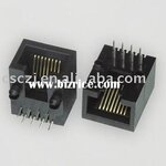
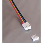
I'm using pic18f Ethernet controller. and i have given a attachment for that rj45 connector to PCB. and 4 pin connector is not UTP. thats just 4 wire parallel connector. Side_Entry_RJ45_Network_Connector.jpg4pn connector.jpg
 

Manufacturer application notes for 100 Mbit ethernet suggests to make the PCB traces between transformer and RJ45 connector not longer than 25 mm. In my understanding, this is mainly for interference reduction.
**broken link removed**

The shown 4-wire connection has a transmission line impedance considerably larger than 100 ohm. I assume that it works even with 100 Mbit ethernet, but it's no good solution. Twisting the RX and TX pairs would improve the signal quality.
 
sorry Fvm. i cant get the answer clearly from you. and i should correct my question. for pcb routing how long distance between network connector rj45 and pic18f67j60 controller can be possible.
 

You should use UTP cable, just like FvM says.

From datasheet https://ww1.microchip.com/downloads/en/DeviceDoc/39762f.pdf

Page 219:

"Since relatively high currents are necessary to operate the twisted-pair interface, all wires should be kept as short as possible. Reasonable wire widths should be used on power wires to reduce resistive loss. If the differential data lines cannot be kept short, they should be routed in such a way as to have a 100Ω characteristic impedance."


I think you will be able to use longer UTP, but for 4-wire (telephone) cable I dont think you can get some distance. Use full cross section UTP cable, and look that is quality cat6,7,8 if possible. Avoid to use some very cheap cat5 cables if you dont have some quality confirmation for that product.

Also replace low cost plastic RJ45 connector with some shielded RJ45 connector module with protection (see datasheet), and do properly connection with cable. If you plan to put that cable into some noise environment maybe consider STP SFTP cables with proper grounding.
 
Last edited:
  • Like
Reactions: neduva

    neduva

    Points: 2
    Helpful Answer Positive Rating
is there anything like data line Tin+/- and Tout+/- should be needed to be in same length. and from **broken link removed** . I've seen that distance between magnetic core and rj45 should be approx 25mm, likely distance between magnetic core and phy in controller may be 25mm or greater. is that correct? can i keep some more distance between that magnetic transformer and phy in controller.

- - - Updated - - -

and what is 100ohm characteristic impedance means
 

distance between magnetic core and phy in controller may be 25mm or greater. is that correct?
Yes, with right impedance.

Transmission line impedance is set by conductor diameter and spacing, permittivity of isolator and possible ground planes or shielding. There are calculators for PCB differential pairs. Cable impedance is specified for RF and network cables, for arbitrary wire geometries it can be calculated according to theoretical electrical engineering text books.
 
  • Like
Reactions: tpetar

    tpetar

    Points: 2
    Helpful Answer Positive Rating
thanks Mr FvM. and still i have a doubt about " is Tin+/- and Tout+/- should be in same length or can variable?". because while routing in pcb there may be some variation in length of the conducting path.
 

There's no length matching required between TX and RX (inter-pair matching). + and - lines should be matched (intra-pair matching).
 
Thanks friends. I prepared one pcb design and given for manufacturing. i have to wait for a week to get that and understand their performance.
 

Status
Not open for further replies.

Part and Inventory Search

Welcome to EDABoard.com

Sponsor

Back
Top