Continue to Site

Welcome to EDAboard.com

Welcome to our site! EDAboard.com is an international Electronics Discussion Forum focused on EDA software, circuits, schematics, books, theory, papers, asic, pld, 8051, DSP, Network, RF, Analog Design, PCB, Service Manuals... and a whole lot more! To participate you need to register. Registration is free. Click here to register now.

[SOLVED] How fast can a BDX33C switch an inductive load?

Status
Not open for further replies.

JohnJohn20

Advanced Member level 4
Joined
Feb 2, 2012
Messages
111
Helped
0
Reputation
0
Reaction score
0
Trophy points
1,296
Activity points
2,377
I have a smartdrive washing machine motor. These are normally driven by a 400VDC power supply using FETs or similar transistors to switch the power to the coils.

My plan is to have a 80V rechargable battery and switch the coil power with BDX33C and BDX34C Darlington pair transistors (because they are cheap and easy to use and I can drive them straight off the 20mA output of a Arduino board).

At 1000 RPM the coils will need about 1 amp switched at 800Hz.

My questions are:
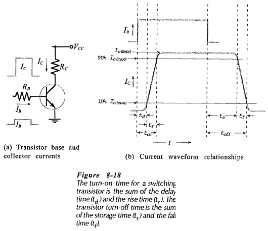
1. How fast can these transistors turn on / off?
2. What is the Turn on / turn off times of these transistors?

The BDX33 data sheet says " They are intented for use in power linear and switching applications. " and " is designed for general
purpose and low speed switching applications. " which is a bit vague.

bdx33-safe-operating-area-jpg.166291
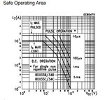
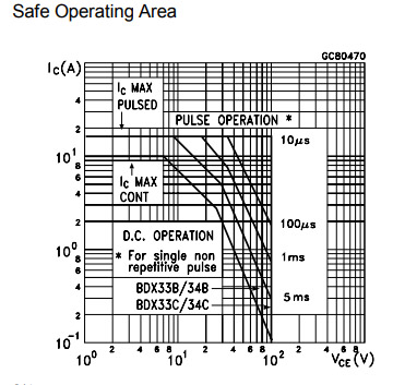
The data sheet does have this graph but I am not sure what it means. Thanks for your time.
 

Attachments

  • BDX33 Safe Operating Area.jpg
    BDX33 Safe Operating Area.jpg
    53.4 KB · Views: 371

Hi,

You show the SOA diagram. It does not show how fast it can switch.
The SOA diagram shows how long it can withstand which power dissipation..before the silicon gets overheated.

I see no problem for a BDX33 to switch with 800Hz.
But BDX33 maybe was up to date 30 years ago. Now there are more modern solutions.
IGBT, MOSFET, SSR or integrated solutions.
The benfits are: easy to control, faster, less power dissipation (don't need a heatsink), maybe features like protection against overvoltage, overcurrent, overheat...

But you are free to choose your own solution.

Klaus
 

But BDX33 maybe was up to date 30 years ago. Now there are more modern solutions.
IGBT, MOSFET, SSR or integrated solutions.
The benfits are: easy to control, faster, less power dissipation (don't need a heatsink), maybe features like protection against overvoltage, overcurrent, overheat...
Thank you Klaus.
All very true, the original drivers used IGBTs or MOSFETs for those reasons. But they generally require a high driver voltage which doubles the building drama.

Can anyone suggest an upper limit of the switching frequency. Could they manage 1MHz?
 

Hi,

The switch rise time, etc., parameters in the electrical characteristics section of the datasheet can be used to estimate switching frequency possible by dividing 1 second by the summed rise and fall, etc. times.

More complicated might be considering MOSFET capacitances (also in datasheet) that need to be charged and discharged for switching on and off the MOS and doing the RC calculations using gate input resistance to arrive at a similar result you can divide 1 second by.

Both approximations but maybe enough to check 1 MHz is possible, should be as MOSFETs are fast - little 2N22222 BJT has fT of 1 MHz.
 

Hi,

stay with 800Hz if possible. 1 MHz is nonsense for a washing maschine motor control.

There is a factor of 1250 between 800Hz and 1 MHz. These are completely different areas. Not comparable.
Example: a car with 80km/hour vs 10.000km/hour.

Klaus
 
even with 150 ohm B-E on the larger xtor in the Darlington - the storage time could be as much as 1uS or more

reverse biased base current will speed up the turn off greatly if you can arrange it - snubbers a good idea if the turn off is fast ....

Xtors turn on pretty fast if you hit them with a small step of base current, < 50nS if you want ...
--- Updated ---

there is a lot of art & science and experience in good base drive ckts ..... ( all done in the 70's )
--- Updated ---

 
Last edited:
You can refer to a recent darlington transistor with similar specifications that comes with switching speed specs TIP142 Complementary power Darlington transistors.

They specify 4 µs toff. Please noticed that negative gate bias removes charge carriers from the pre-deriver but not from the main transistor.
 

    JohnJohn20

    Points: 2
    Helpful Answer Positive Rating
Why do you want to switch at such a high frequency?
The motor certainly doesn't need that.
I wanted to add PWM control if possible. Sorry I should have added that to my question.
I will not need 1 MHz but I was looking for an upper limit so I threw that out there.
The Arduino NANO PWM frequency can be set to ~32kHz (or ~64kHz depending on which PWM pins are used) which gives about 30uS (or 15uS) which sounds quite feasible.

Thanks everyone.
 

Status
Not open for further replies.

Part and Inventory Search

Welcome to EDABoard.com

Sponsor

Back
Top