Continue to Site

Welcome to EDAboard.com

Welcome to our site! EDAboard.com is an international Electronics Discussion Forum focused on EDA software, circuits, schematics, books, theory, papers, asic, pld, 8051, DSP, Network, RF, Analog Design, PCB, Service Manuals... and a whole lot more! To participate you need to register. Registration is free. Click here to register now.

How does this VCO work?

Status
Not open for further replies.

aj_silverthunder

Full Member level 3
Joined
Jul 30, 2009
Messages
179
Helped
0
Reputation
0
Reaction score
0
Trophy points
1,296
Location
asia
Activity points
2,601
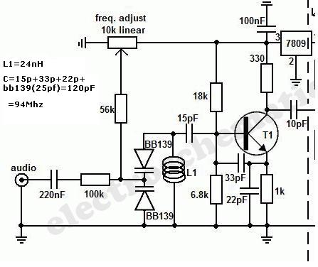
guys tell me how does this VCO works, is the frequency of the oscillator is 94Mhz? How is the stability? Does it have frequency drift?

79_1260128414.jpg
 

Re: oscillator! doubt

With the values given it will be adjustable between about 80MHz and 120MHz. About the drift: Well let's say all oscillators have some drift. This design will be prone to temperature drift and will suffer from bad phase noise, as it is free running and a less than optimal design overall.

Taking the output on the collector will also give high levels of harmonics as can be seen from the scope trace.
 

oscillator! doubt

which oscillator has a good frequency stability ! colpitt,hartely,wein bridge,etc,,,,,,,,,
 

oscillator! doubt

A crystal oscillator or a modern frequency synthesizer (crystal controlled) have excellent frequency stability. They are used in all the new MP3 to car radio FM stereo transmitters.
Rohm company make a range of these modern FM stereo transmitter ICs.

A modern FM radio does not work if the transmitter frequency is not accurate and not produced by a crystal.

EDIT:
Your circuit is extremely old (30 years old?). The BB139 varicap diode is not made anymore.
 

oscillator! doubt

then i want a 20 to 30pF varicap can tell me some name of the varicaps please!!
 

Re: oscillator! doubt

I am also trying to build this same circuit. I have acquired all the components shown in diagram. I even have BB139 with me. THEY WERE DIFFICULT TO FInd thoUgh. i SOLDERED THIS CIRCUITRY ON A VERO BOARD. bUT I AM NOT GETTING ANY progrss. I checked the AC voltage at the I/P. There were variations of 0 to 2 volts. but as i proceeded to check the voltages on the varicaps, i did not find any voltage over there.

Please help.!
 

Re: oscillator! doubt

I checked the AC voltage at the I/P. There were variations of 0 to 2 volts.
That is the audio that modulates the transmitter.

i proceeded to check the voltages on the varicaps, i did not find any voltage over there.
The varicaps are fed a variable DC tuning voltage plus very low current AC audio that modulates the DC.
 

Re: oscillator! doubt

That is the audio that modulates the transmitter.


The varicaps are fed a variable DC tuning voltage plus very low current AC audio that modulates the DC.

Can you please elaborate. If there was AC variations going towards the varicaps, then the AC should have passed through the Varicaps. Shouldn't it? And the variable DC voltage will be blocked. Basically i will be happier to know the working step by step of this circuit.

I am trying to focus, but cant understand. Isn't there any book that deals with the practical communications circuits such as this?
I just find books with lots of theory theory and concepts only.
 

Didn't you learn how a varicap (varactor) diode works?? When the voltage across it is changed then its capacitance changes.
When the capacitance is changed in an LC tuned circuit then its frequency is changed.

The variable DC is from a potentiometer for tuning the radio frequency.
The audio modulates (changes) the voltage across the varicap (varactor) diodes which changes their capacitance and modulates the radio frequency (FM).

Most simple FM transmitters do not have a varicap (varactor) diode. The audio modulates the capacitance of the oscillator transistor.
 

Status
Not open for further replies.

Similar threads

Part and Inventory Search

Welcome to EDABoard.com

Sponsor

Back
Top