Continue to Site

Welcome to EDAboard.com

Welcome to our site! EDAboard.com is an international Electronics Discussion Forum focused on EDA software, circuits, schematics, books, theory, papers, asic, pld, 8051, DSP, Network, RF, Analog Design, PCB, Service Manuals... and a whole lot more! To participate you need to register. Registration is free. Click here to register now.

How does this spring back push button work in this RF circuit?

Status
Not open for further replies.

Escaflone

Newbie level 4
Joined
Aug 19, 2007
Messages
5
Helped
0
Reputation
0
Reaction score
0
Trophy points
1,281
Activity points
1,319
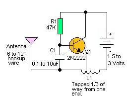
Hello , i have a question regarding this rf circuit ...
can anyone help me with this ?

on this circuit , if i add a spring back push button to the batteries in line , and whenever i push that button once , does it actually sending out a "pulse" as in a "1,0" signal out to the ant ??? and then to the receiver ???

Added after 1 minutes:

87_1187523239.jpg
 

Re: rf circuit!

hmm... then what does this circuit work???
 

Re: rf circuit!

actually the circuit fixes its resonant cavity frequency using the capacitor and the tapped inductor.... but the main problem here is when you switch on and off the supply the inductor would exhibit inductive kickback which would be disastrous for your circuit.....
 

Re: rf circuit!

i found this circuit at
**broken link removed**

if this is the case , what was it sending out through the ant all the time ?

what was this circuit used for , anyone know???
 

Re: rf circuit!

when you change the tapping ratio or the capacitorof the resonant circuit the frequency of the output varies.... this is effectively a FM modulator the only thing is you gotta use a circuit to change the tapping based on the input signal....
 

Re: rf circuit!

how will you add the circuit in and where will you input the signal from let say a pulse out ... is it possible to use a oscillator in this circuit ???

sorry, i m totally new in this field and still learning hard...
 

Re: rf circuit!

you can put a input signal circuit which varies the capacitor value or the inductor value... for varying the capacitor value say you can use a varicap diode.... the pulse effectively consists of a sudden amplitude variation so a sudden change in resonant frequency will lead to it....

the capacitor and tapped inductor is already working as a oscillator(passive one)...
 

Re: rf circuit!

i found this circuit at
**broken link removed**

if this is the case , what was it sending out through the ant all the time ?

what was this circuit used for , anyone know???

What count as 1 or 0 depends on what you want to get. This particular circuit is a good example of QD (Quick and Dirty) oscillator that may generate whatever is possible. Ratio of 1/3 is well known value for three-point oscillators, you may adjust it slightly, but it will not fix all the RF problems with this circuit.

Let's say you have a coil with about 25 turns of reasonable thick wire and about 5 mm of coil diameter. In such case you get inductance about 1e-6H and frequency range will be roughly between 50 and 500 kHz with displayed capacitors values.

May be it can be used to send 1 and 0 signals, but you definitely will have a problem with FCC.

Good luck with your experiments
 

Re: rf circuit!

Thanks , i will try it out!

Added after 1 hours 30 minutes:

Don`t mind if i ask this ...

this badly drawn schematic, i followed a 27mhz toy car transmitter circuit board to drawn out...

the circle thing is bottom right was a tesla coil with 5 pin connection.
can help me identify the tx circuit and how it actually work ?
i tried tracing out the circuit and found pin 8 and 10 of the ic linked to the circuit .
The ic was SM6136, pin9 was Vdd and pin3 was Gnd... pin 8 was where the unmodulated data came out but pin 10 was "PC" which i doesn understand what it was for even in the datasheet as it was in chinese version as made in china.

can i replace the tesla coil with oscillator, how to do that?
possible to make just the transmitter out of this circuit with a line to feed in data for transmitting ???


Added after 5 hours 46 minutes:

i came across this schematic


the transmitter part looks the same as the one i traced out above... but the connection of the transistor were kind of differents ...
can anyone help me to understand ?
 

Status
Not open for further replies.

Part and Inventory Search

Welcome to EDABoard.com

Sponsor

Back
Top