matin-kh
Member level 3

- Joined
- Nov 9, 2013
- Messages
- 67
- Helped
- 0
- Reputation
- 0
- Reaction score
- 0
- Trophy points
- 1,286
- Location
- iran
- Activity points
- 1,955
Hello!
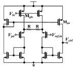
I extract this integrator from a paper which is used in AGC circuits to produce control voltage of VGA. I can not understand how it can perform as an integrator because it is a symmetrical CMOS OTA which amplifies the differnce between Vpeak and Vref and if we consider the output capacitor as the capacitor of integrator an amplifier which work as an Op Amp is absent yet.
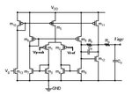
the integrator shouldn't be like fig.2? so I can't understand how the fig.1 could act as integrator and can control the gain of VGA?
and what is the duty of two R?
Could you please help me?


with best regards
Matin
I extract this integrator from a paper which is used in AGC circuits to produce control voltage of VGA. I can not understand how it can perform as an integrator because it is a symmetrical CMOS OTA which amplifies the differnce between Vpeak and Vref and if we consider the output capacitor as the capacitor of integrator an amplifier which work as an Op Amp is absent yet.
the integrator shouldn't be like fig.2? so I can't understand how the fig.1 could act as integrator and can control the gain of VGA?
and what is the duty of two R?
Could you please help me?


with best regards
Matin


