Continue to Site

Welcome to EDAboard.com

Welcome to our site! EDAboard.com is an international Electronics Discussion Forum focused on EDA software, circuits, schematics, books, theory, papers, asic, pld, 8051, DSP, Network, RF, Analog Design, PCB, Service Manuals... and a whole lot more! To participate you need to register. Registration is free. Click here to register now.

How does this circuit work ?

Status
Not open for further replies.

Okada

Banned
Joined
Jun 16, 2016
Messages
1,159
Helped
129
Reputation
252
Reaction score
129
Trophy points
63
Activity points
0
How does this circuit work ?

As it is a PIC based circuit I am asking the question in Micocontroller section.

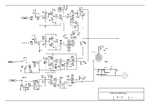
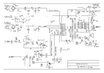
Please see the attached circuits.

The Transformer is a Iron-Core Transformer. The FB Winding is used for Feedback to AC to adjust the output voltage.

The PIC circuit has a ZCD circuit. Don't know how it works.

There is a Relay 30 Amps. Why is it used ?

The circuit is of a 220-V 50 Hz Inverter.

My client says that the same transformer is used for both output (220V) and for charging the battery.

7.5V is stepped to 220V. 15V from Feedback winding goes through bridge, filter and zener to ADC for monitoring the output voltage level.

He says that when there is mains then the high side mosfets will be off and the low side mosfets will works as boost converter for charging the battery. If it is right then what signals I have to apply to the low side mosfets for charging the battery ?
 

Attachments

  • Controller.gif
    Controller.gif
    66.8 KB · Views: 90
  • driver_stage.gif
    driver_stage.gif
    56.2 KB · Views: 97

It is UPS. Simple schematic for old battery protected inverted for emergency power supply. When 220V line is present, H-bridge works as active rectifier and charging the battery. When power cuts, it becomes an inverter and supply the load with pure sine voltage. I think, it is about 20 years old. I have seen such devices very long time ago.
 

So, no special code has to be written for the PIC for charging mode ? Why is the ZCD used ?
 

ZCD is used for control charging current by changing switching phase and to syncronise the voltage when switching from battery power to line power. It takes about 1s to switch because of phase aligment.
What do you mean 'special code'? Code is pretty comlicated for this device.
 

Its a bit tricky for me to see (my normal browsing laptop died and I have a small display for now) but I cant see any connection to the relay - this would suggest an aux device - maybe a louder claxon or or external signal line or some such? Does the device have an output signal socket or anything like that.
 

What do you mean 'special code'? Code is pretty comlicated for this device.

I am replacing the PIC16F72 because it is old and is not available here. Also it code uses timers to generate the PWM as 16F72 doesn't have PWM module. I am going to use 18F26K22 or 18F46K22. I will provide Full-Bridge Signals to the FET drivers. I am adding an LCD which displays

Battery Charging
Battery Fully Charges
Mains Voltage - when mains present
Output Voltage - when no mains
Mains frequency - when mains present
AC frequency when Inverter is ON

I will not be using Timers to generate the signals for the FET drivers.

I have one problem.

I need to use 20 KHz SPWM but I also need a 1.5 to 2 KHz PWM for Buzzer. how to get different PWM frequencies from the same PIC ? Should I use a separate 12F1840 for Buzzer ?

I am using mikroC PRO PIC Compiler and its PWM library. If PWM library is used then PWM frequencies for all the channels will be that of the frequency set using the last call of

]code]
PWMx_Init(frequency);
[/code]
 

You have only one problem how to turn on your buzzer? Seriously? All other functionality works perfect?
 

No, I have not yet tested it. I am using the same circuit with a different 18F PIC. ADC is used in the same way. Full-Bridge Signals (4 Signals) are generated for the FET drivers.

LCD display required messages.

It has to be tested in hardware.

Buzzer has to beep twice when mains fails or mains return. Next week the code will be tested without buzzer code. The only issue now is about the buzzer.

I will feed the ZCD output to T0CKI pin (8 bit counter)

I want to know how to synchronise the AC signal. My SPWM when starts it starts at 127 PWM duty. So, the SPWM signal doesn't start to 0 degree.
 

Status
Not open for further replies.

Similar threads

Part and Inventory Search

Welcome to EDABoard.com

Sponsor

Back
Top