Continue to Site

Welcome to EDAboard.com

Welcome to our site! EDAboard.com is an international Electronics Discussion Forum focused on EDA software, circuits, schematics, books, theory, papers, asic, pld, 8051, DSP, Network, RF, Analog Design, PCB, Service Manuals... and a whole lot more! To participate you need to register. Registration is free. Click here to register now.

how does this alarm speaker amplifier circuit to work?

Status
Not open for further replies.

hero0765

Member level 2
Joined
Sep 15, 2008
Messages
52
Helped
2
Reputation
4
Reaction score
2
Trophy points
1,288
Location
China
Activity points
1,605
hi:
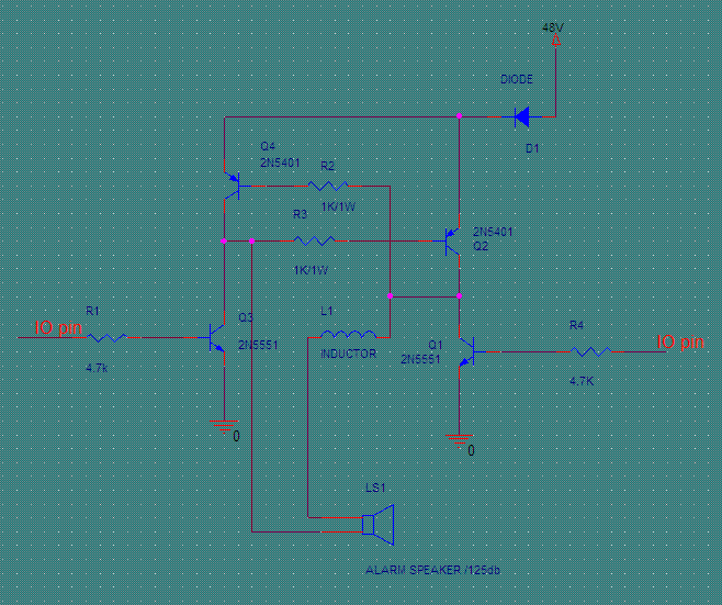
here is a alarm speaker amplifier circuit , there is two MCU IO pins to driver the circuit to make the alarm speaker sound different alarm voice. But I have two question here :
1. the circuit is made of four transisters. how do the four transisters work?
2. how do I change the MCU IO signal to make the circuit work?

thanks!
 

Attachments

  • 1.bmp
    1 MB · Views: 89

This circuit works like a bridge: Q3-Q2 or Q1-Q4, but not both pairs at the same time, so both inputs should not be “H” at the same time ..
To generate sound you need one of MCU pins to produce a square wave and vary the frequency if you want to change the tone ..

:wink:
 

You need a square wave on one I/O pin and the inverse on the other.

Keith
 

Status
Not open for further replies.

Similar threads

Part and Inventory Search

Welcome to EDABoard.com

Sponsor

Back
Top