Continue to Site

Welcome to EDAboard.com

Welcome to our site! EDAboard.com is an international Electronics Discussion Forum focused on EDA software, circuits, schematics, books, theory, papers, asic, pld, 8051, DSP, Network, RF, Analog Design, PCB, Service Manuals... and a whole lot more! To participate you need to register. Registration is free. Click here to register now.

How does the 5A Constant Voltage/Constant Current Regulator circuit using LM317 works

Status
Not open for further replies.

matbob

Full Member level 2
Joined
May 15, 2008
Messages
128
Helped
26
Reputation
52
Reaction score
12
Trophy points
1,298
Location
KERALA
Activity points
2,061
Dear All,

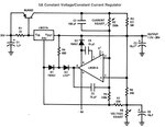
I would be really happy if someone could explain how the circuit: 5A Constant Voltage/Constant Current Regulator given in the LM317 datasheet works. I have built this circuit and it works like a charm. Really good circuit for experiment purposes.

Circuit:
CVCC.JPG

What are the purposes of R4, R7, D2, C5?
Is the LED for indication purpose only?
 

Dear matbob
Hi
It is simple , try to separate each part and one by one analyze it !
one of those LEDs are for over load and the other is for usual behavior indication .
The R2 and R5 will be feed back networks ( for current sampling ) and the R3 called sense current . and i think C5 is for loop stability ( compensation network ).
Best Wishes
Goldsmith
 
Hi Matbob,
since you have already built the circuit, you can try to put the R4, R7, D2, C5 and you will see the differences. It should be get some different results possibly better. Try it and let us know about your positive or negative results

Regards,
 

Mainly you have 3 subcircuit:

1. the transistor: it is used to supply the wanted current
2. The LM317: it is used to keep the output voltage constant
3. The op-amp based network: it is used to supply a feedback to the LM317 providing also overcurrent protection

As said the current will be passing almost through the transistor, then the collector voltage will be higher than the output depending from the sourced current "I". It will be Vo+R3*I. This voltage is sent to the inverting-input of the op-amp divided by R2-R5 then the higher the current the lower the output of the op-amp. The inverting pin is also function of R6-R8 that set the output voltage acting directly on Vadj. The non-inverting input is directly connected to Vout, then if the voltage on the inverting pin is higher than Vout the op-amp out will be negative (the op-amp will sink current) otherwise positive. The LED has the double function: indicate the protecting function is firing and not allow the positive voltage to reach R4. If the non-inverting pin voltage increases (i.e. the output current is increasing) the output of the op-amp will start to decrease the Vadj (then the Vout) once the LED threshold has reached (roughly 1.5V). The voltage on the LED is the difference between the op-amp output and Vout (through R4 that fixes the current). D2 and C4 are compensation and balancing network not used if you are using other op-amps.
 
Last edited:
Hi
How to modify this circuit to enable user feeding the required ampere? Required Output range is 1 microA to 15 mA and 10-30v.
 
Last edited:

Status
Not open for further replies.

Part and Inventory Search

Welcome to EDABoard.com

Sponsor

Back
Top