Continue to Site

Welcome to EDAboard.com

Welcome to our site! EDAboard.com is an international Electronics Discussion Forum focused on EDA software, circuits, schematics, books, theory, papers, asic, pld, 8051, DSP, Network, RF, Analog Design, PCB, Service Manuals... and a whole lot more! To participate you need to register. Registration is free. Click here to register now.

how does a transistor amplify?

Status
Not open for further replies.
Re: how does the transistor amplify ?

Almost every signal source is a fairly high resistance current source.
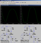
...every signal source?
Here is a common-emitter transistor with a sinewave voltage source. The input is a sinewave but the output isn't:
Yes - no surprise.
DC supply of 10 volts. DC operating point of app. +5 volts. Output swing of (+/-) 4 volts. No signal feedback. Results as expected. Bad application.
 

Re: how does the transistor amplify ?

The description of the bipolar transistor as voltage controlled device is substantiated in the transistor model, it's primarly a matter of theory. It's another thing to refer to this description in circuit calculation. Although the voltage controlled model is leading to a straightforward calculation in my view, you may prefer a behavioral transistor description as current amplifier in some cases.

In any case, the theoretical description isn't directly related to circuit design. Source and load impedances are given conditions which are reflected in a respectively optimized amplifier circuit. Linearity and stable gain are primarly achieved by feedback. I agree that the inherent linearity of a transistor without feedback is higher in current than in voltage control. But the gain is still largely affected by temperature and type variations.

In so far it's neither the better amplifier concept nor a foundation for a current control transistor theory.
 
Re: how does the transistor amplify ?

. The collector of a previous transistor stage has the resistance of its collector resistor.
I don`t think that this is a good argument.
You always have two alternatives to find the gain of two stages in series:

1.) Gain of the 1st stage (without the 2nd stage connected): Vout,1/Vin,1=-g*Rc1.
Thus, the 2nd stage is feeded with Vout,1 through an output source resistor Rc,1 and a voltage Vin,2 is developed across rin,2:
Vin,2=Vout,1*rin,2/(r,in2+Rc1)=-Vin,1*g*Rc1*rim,2/(r,in2+Rc1)=-Vin,1*g*(Rc1||rin,2).

2.) This is, of course, the same expression for the voltage at the base node of the 2nd stage (Vin,2) we can find if - from the beginning - the complete load resistance Rc1||rin,2 is considered.

Thus, it is not true that the 2nd stage is feeded by a kind of "current source". Both calculations give a voltage at the base of the 2nd stage.
 

Re: how does the transistor amplify ?

To the Ineffable All,

The name of this thread is something like "How does a transitor (BJT) Amplify?". This question can only be answered and explained by addressing the physics of the BJT, which I tried to do in post #13 of this thread. Any model you can dream up only shows what a transistor does, not how it does it. Similarly, any components or souces you attach to the transistor to change the circuit impedance or whatever other reason will not affect the inherent ability of the transistor to amplify.

Ratch
 
  • Like
Reactions: LvW

    LvW

    Points: 2
    Helpful Answer Positive Rating
Re: how does the transistor amplify ?

Here is a common-emitter transistor with a sinewave voltage source. The input is a sinewave but the output isn't:

Audioguru - I have played a little with my simulator.
I have used your circuit for two different analyses:

1.) Following your recommendation, I have created a "moderate" current source using an additional series resistor Rs=25kohms between the signal source (Vs=25mV) and the base node.
As a result, the gain was, of course reduced (app. A=-31) and the quality of the output signal was much better (very good THD). Output amplitude app. 1.5 Vpp.

2.) Using the same input voltage (25 mV) - without the series resistor - but with signal feedback (Re1=240k in series with Ze2=760k||100µF) the result was exactly the same:
Gain A=-31 with the same THD value.
_____________________

As stated above by FvM, this result cannot serve as an argument for current control. We just have two different circuit alternatives, however, the principle function of the BJT is the same in both cases.
 
  • Like
Reactions: FvM

    FvM

    Points: 2
    Helpful Answer Positive Rating
Re: how does the transistor amplify ?

Audioguru - I have played a little with my simulator.
I have used your circuit for two different analyses.
Yes, negative feedback reduces gain and distortion.
With a gain of 1 like a piece of wire then the distortion is nice and low.
 

Re: how does the transistor amplify ?

Yes, negative feedback reduces gain and distortion.
With a gain of 1 like a piece of wire then the distortion is nice and low.

Nevertheless, I hope you got the real meaning of my simulation results.

I have a little supplement:

If you increase the input signal from 25 to app. 120mV - with the series resistor of 25 kohms (as preferred by you) - we get about the same output swing as in your example (post#20) and about the same distortions!!
Question: Where are the advantages of a large source resistance?
 

Re: how does the transistor amplify ?

Nevertheless, I hope you got the real meaning of my simulation results.

I have a little supplement:

If you increase the input signal from 25 to app. 120mV - with the series resistor of 25 kohms (as preferred by you) - we get about the same output swing as in your example (post#20) and about the same distortions!!
Question: Where are the advantages of a large source resistance?
Your output is severely clipping. If your input is reduced to a peak of 85mV then the distortion is about half of it is without the 25k input series resistor. The 25k resistor makes a poor current source but it is better than a voltage source.
 

Attachments

  • input 25mV and 120mV.png
    input 25mV and 120mV.png
    44.9 KB · Views: 66
  • input 25mV and 85mV.png
    input 25mV and 85mV.png
    32.9 KB · Views: 68

Re: how does the transistor amplify ?

Your output is severely clipping. If your input is reduced to a peak of 85mV then the distortion is about half of it is without the 25k input series resistor. The 25k resistor makes a poor current source but it is better than a voltage source.

Two comments:

1.) Surprisingly, the 2N3904 models in PSpice and LTC differ considerably. I didn`t observe such clipping effects during my simulations with PSpice as shown in your display (left figure).
The DC collector voltage in PSpice is 6.75V and in LTC only 6.06V. This explains the difference.
Nevertheless, this does not touch at all the principle under discussion.

2.) The comparison of your simulation results as shown in the right-hand figure is rather meaningless. Because:
You are comparing two circuits with different gain values (about the same output, but left: 25mV input, right: 85mV input). The situation will change drastically if you reduce the gain of the left circuit to the same value of the right circuit using emitter feedback (as mentioned in my post#25).
 

Re: how does the transistor amplify ?

Two comments:

1.) Surprisingly, the 2N3904 models in PSpice and LTC differ considerably. I didn`t observe such clipping effects during my simulations with PSpice as shown in your display (left figure).
The transistor is far from clipping (at the top of the waveform) caused by becoming cutoff. Instead it is showing that the base-emitter voltage change causes a logarithmic change in the collector current which is not linear. The bottom of the waveform is actually expanded which is the opposite of the top.

2.) The comparison of your simulation results as shown in the right-hand figure is rather meaningless. Because:
You are comparing two circuits with different gain values (about the same output, but left: 25mV input, right: 85mV input). The situation will change drastically if you reduce the gain of the left circuit to the same value of the right circuit using emitter feedback (as mentioned in my post#25).
No, the gain values are exactly the same. The circuit with the 25k series input resistor has its input attenuated by the 25k resistor so of course the input level to this resistor was increased.

Since the 25k resistor made a lousy current source I increased it to 470k but then my waveform was clipped at the bottom so I re-biased the transistor slightly to push the waveform up. Now the output levels are the same but the differences in distortion are obvious.
 

Attachments

  • input 25mV and 900mV.png
    input 25mV and 900mV.png
    30.1 KB · Views: 62

Re: how does the transistor amplify ?

No, the gain values are exactly the same. The circuit with the 25k series input resistor has its input attenuated by the 25k resistor so of course the input level to this resistor was increased.

Since the 25k resistor made a lousy current source I increased it to 470k but then my waveform was clipped at the bottom so I re-biased the transistor slightly to push the waveform up. Now the output levels are the same but the differences in distortion are obvious.

1.) When I speak of "gain", of course, I mean the gain as it is defined as the output-to-input ratio.
Because the output swing of both circuits in your post#28 (right figure) is about the same but the input signals differ by a factor of 85/25=3.4, I conclude that the overall gain is different. OK?
I cannot understand how the gain values should be "exactly the same".

2.) Of course, this is the case also with the example in your recent post - but with a drastically increased differnce in gain values.
Again, in both cases the output swing is app. equal - however, the applied input voltage differs by a factor of 900/25=36.

3.) Question:What do you think, how the output would look like if you would decrease the left circuit using feedback to an overall gain which is similar to the gain of "your" circuit (with 470k series resistor) ? Try it!
___________________

Finally, I think it does not make much sense to continue this kind of discussion because we speak about different approaches.
For my opinion - in contrast to yours - the additional attenuation caused by the series resistor must of course taken into account during gain calculation. There simply is no other alternative.
That was the reason I have mentioned that the comparison is not fair. We cannot compare the output waveform of circuits with different gain values.

In contrast: The only comparison which makes sense is to compare two different methods for reducing the voltage gain of two circuit versions to the same value:
1.) Series resistance (which mimics a current source and - at the same time - causes base-emitter input voltage attenuation),
2.) Signal feedback (which also causes base-emitter input voltage attenuation).
 

Re: how does the transistor amplify ?

I compared the series input resistor mimicking a current source input with emitter negative feedback. The series input resistor reduced the distortion a lot but the emitter negative feedback looks a little better.
 

Attachments

  • resistor input and emitter feedback.png
    resistor input and emitter feedback.png
    44.7 KB · Views: 76

Re: how does the transistor amplify ?

The series input resistor reduced the distortion a lot but the emitter negative feedback looks a little better.
The THD numbers acording to LTspice are 7.4 % (current controlled) versus 1.9 % (voltage controlled with feedback). The original voltage controlled circuit from post #28 has 21.4 % THD.
 

Re: how does the transistor amplify ?

I hope - as a kind of conclusion - that the OP hopefully was able to learn something about the different alternatives and approaches which exist for describing/calculating the amplifying characteristics of a bipolar transistor.
 
  • Like
Reactions: FvM

    FvM

    Points: 2
    Helpful Answer Positive Rating
Status
Not open for further replies.

Part and Inventory Search

Welcome to EDABoard.com

Sponsor

Back
Top