Continue to Site

Welcome to EDAboard.com

Welcome to our site! EDAboard.com is an international Electronics Discussion Forum focused on EDA software, circuits, schematics, books, theory, papers, asic, pld, 8051, DSP, Network, RF, Analog Design, PCB, Service Manuals... and a whole lot more! To participate you need to register. Registration is free. Click here to register now.

How does a magneto ignition operates ?

Status
Not open for further replies.

Externet

Advanced Member level 2
Joined
Jan 29, 2004
Messages
579
Helped
28
Reputation
58
Reaction score
29
Trophy points
1,308
Location
Mideast US
Activity points
5,657
Hi. Small engines like lawn mowers get their spark from magnetos, from a passing magnet at the flywheel.

Is the primary winding acting raising the voltage while the magnet approaches, reaching a peak value and then decreasing, sort of a sine peak ? The spark occurring when the magnetic field is decreasing from its maximum ?

If the primary waveform from the induction, instead of decreasing sinusoidally is abruptly shut off at peak; would the high voltage generated for the spark be considerably higher ?

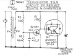
Am asking as found a gadget/circuit intended to do that; if I understand what it is doing -attached image borrowed from the web-
At left, the magneto secondary and primary windings. How does the shorting of primary winding detects the peak to collapse the magnetic field, or, am I understanding it wrong ? How does it work ?
 

Attachments

  • Screenshot from 2018-06-04 17:00:01.png
    Screenshot from 2018-06-04 17:00:01.png
    294.9 KB · Views: 177

That's no regular magneto ignition circuit, the breaker contact is missing. I don't see how the transistor switch should be able to interrupt the primary current at the exact ignition time. Study standard magneto circuits.

Electronic ignition systems need a sensor with precise timing that replaces the breaker contact, e.g. a hall effect sensor. It would be theoretically possible to derive the ignition trigger from the induced voltage zero crossing, but existing ignition systems aren't designed for this purpose and don't provide a means to adjust the coil voltage timing.
 

Thank you.
There may be several magneto flavors; for a small engine, the typical is like pictured below; the passing of the magnet on the flywheel produces the spark tension at the heavily insulated wire.

The small spade terminal may be the non-ground primary winding end used to shut down the engine when grounded by a keyswitch or contact. There is no points, capacitor. It is self performing.
A passing magnet creates the spark with no other components needed, unlike the Kettering system.

- - - Updated - - -

If the spade terminal in the picture below is connected to the transistor circuit (top rail R2, R1, Q1, cathode) on the first picture; would it short that rail to ground at a certain moment, causing spark ?
 

Attachments

  • Magneto.jpg
    Magneto.jpg
    42.8 KB · Views: 60
Last edited:

The spark is generated by opening the break contact or an electronic switch, not closing it. I doubt that the shown ignition switch works without some kind of break switch, because the induced voltage is only a small fraction of the fly back voltage that can be generated by interrupting the primary current flow, and hardly sufficient to cause an ignition spark.
 

The spark is generated by opening the break contact or an electronic switch, not closing it. I doubt that the shown ignition switch works without some kind of break switch, because the induced voltage is only a small fraction of the fly back voltage that can be generated by interrupting the primary current flow, and hardly sufficient to cause an ignition spark.

It does. Q1 is the break switch.

As the voltage increases due to proximity to the magnet, Q2 is turned on, which causes Q1 to immediately turn off, which collapses the field and results in a spark. There is a small amout of adjustability of the timing cycle by rotating the entire assembly.
 

I don't doubt that Q1 can act as electronic break switch, I questioned that it does at the correct time if the system isn't designed for. In other words, the naive idea of a homemade electronic break switch could result in worse motor performance.

There is a small amount of adjustability of the timing cycle by rotating the entire assembly.
If the motor is designed for this kind of adjustment.

My quoted statement in post #4 is however referring to the #3 post claim, the ignitor in the photo works without a mechanical or electronic break switch. Don't say it's absolutely impossible, but I haven't seen one yet.
 

My quoted statement in post #4 is however referring to the #3 post claim, the ignitor in the photo works without a mechanical or electronic break switch. Don't say it's absolutely impossible, but I haven't seen one yet.

My Honda engine (1 cylinder) has the ignition like the photo. These small horsepower engines no longer have mechanical breakers (I know, because I recently gave my engine an overhaul and was shocked to not find any breaker switch to de-pit and set!). I assumed that the schematic shown in #1 was a circuit trace of the PCB embedded in the ignition module itself (and not some homemade version).
 

I believe there is no electronic circuits in a stock magneto; just the coils. When the flywheel magnet passes past the coil, the magnetic field collapses inducing the spark.

Most of this comes from a contraption added/installed in my mower engine, its schematic supposed to be the right section of the first schematic in this thread.

----> https://pickersyard.weebly.com/atom-universal-electronic-ignition-module.html

That I would like to understand... I have the 'green' one.
 
Last edited:

STMicro had an online app note which described exactly what you require.
They even sell, if I remember correctly- an integrated solution.
 

I believe there is no electronic circuits in a stock magneto; just the coils. When the flywheel magnet passes past the coil, the magnetic field collapses inducing the spark.
Again, the dV/dt is too low to get sufficient voltage without some kind of breaker (may be electronical).

The add-on module vendor claims to "Automatically adjust the ignition timing to the same firing position as the original breaker points".
Adjustment is in fact necessary, but I don't see how it could be achieved with the module.
 

Status
Not open for further replies.

Part and Inventory Search

Welcome to EDABoard.com

Sponsor

Back
Top