Continue to Site

Welcome to EDAboard.com

Welcome to our site! EDAboard.com is an international Electronics Discussion Forum focused on EDA software, circuits, schematics, books, theory, papers, asic, pld, 8051, DSP, Network, RF, Analog Design, PCB, Service Manuals... and a whole lot more! To participate you need to register. Registration is free. Click here to register now.

How do to calculate the value of choke inductor in my system?

Status
Not open for further replies.

alexdemo

Newbie level 5
Joined
Dec 24, 2017
Messages
9
Helped
0
Reputation
0
Reaction score
0
Trophy points
1
Activity points
72
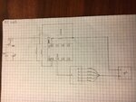
I created a matching network between a 50ohm antenna and a chip with 63-j199 impedance. I have been told that on the 'ant -' pin I have to insert a choke inductor to act as a filter but I do not know how to calculate this inductance value. I saw that the formula XL=2*pi*L is used to get the value of the choke but I would need a clear explanation about its use. My operating frequency is 866Mhz. Thanks
 

I have been told that on the 'ant -' pin I have to insert a choke inductor to act as a filter but I do not know how to calculate this inductance value.

A filter for what?

What is an 'ant -' signal?

If you're putting in an inductor to act as a choke, design it so that it has (as a minimum) an impedance at your frequency at least 10 times the impedance of your system at the point where your inductor will connect. You also will want your inductor to have a SRF (Self Resonant Frequency) as close to your frequency as you can.
 
IMG-3228.jpg

My system consists of a 50ohm antenna connected with SMA, a matching network between the antenna and my chip. I have been told to insert a choke on pin 'ant-' in order to have a filter, but I need to know the inductance value of this choke. With matching network I adapted the impedance of the chip to 50 ohms of the antenna and now I do not know how to find the right value of my choke. Based on what you told me, I have to consider an impedance of 500ohm considering that my system is 50ohm, right?
 

Attachments

  • IMG-3228.jpg
    IMG-3228.jpg
    507.9 KB · Views: 161
Last edited by a moderator:

So i have to do 500=2*pi*866Mhz*L and i have to solve the equations in order to know L? In particular the choke is on the negative side, i don’t know because you said ‘V+’. Also you could tell me why 500ohm is enough as impedance of the choke?
 

Based on what you told me, I have to consider an impedance of 500ohm considering that my system is 50ohm, right?

Select an inductor with at least an impedance of 500Ω (the higher the better) with an SRF as close to 866MHz as you can. This is your V+ line, so your current requirements need to be considered. With these three requirements known, you can now select your inductor.

- - - Updated - - -

EDIT: My bad - I said that the SRF should be as close to 866MHz as you can get. This is incorrect for a choke. You do want the impedance of the inductor to be > 10 times your system impedance, but you need your SRF to be as high as you can get. You definitely do NOT want it to resonate at your freq of operation - to do so will cause it to look like a small resistance to ground (the SRF of a coupling cap should be at your freq). For this case, you need to know the value of the inductor at your operating freq in order to calculate the XL of your choke. This might be something that you will have to measure yourself if you can't find a manufacturer's graph of the value. If the SRF is below your freq, then it will appear as a capacitor and shunt most of the signal to ground. The selection of an inductor for this application will usually lead to a trade-off - the need to have an SRF higher than your freq, the desire to have an XL ten times the Zo and the current carrying capability. What works best for you will probably require some engineering decision making on your part.
 

Sorry, I didn't understand your problem well, no I see more what you want. Figure helped.
But I still don't know what is the purpose of the 'ANT-' pin and why did you wrote VSS also on the figure there?
Is there a differential LNA at the input? Then you should use a balanced matching network, maybe, and not a choke.
https://analog.intgckts.com/impedance-matching/lumped-lc-balun/
Describe more about what are behind the pins of the chip, then we can help more. Oh, and XL=2*pi*f*L correctly, you wrote XL=2*pi*L.
 

Sure, regarding SRF you're absolutely right.
In particular i have inductors of 39nH, using one of them i get: XL=2*pi*866Mhz*39nH, so XL=212,2ohm. Do you think I could use more inductors in series to reach 500ohm or more? Inductance-Frequency Characteristics is represented in datasheet, the graph shows that the inductor value remains about 39nH at my working frequency.

Datasheet: **broken link removed**

As you told me, the impedance of the choke is to be > 10 times my system impedance (50ohm), but there is a reason, or a theory, of why we need to be > 10 times? Because I have to report in the document the method used.
Anyway, do you think my schematic circuit is done correctly? Because before you mentioned v + while the choke is on the negative side.
Thank you for your availability and kindness

- - - Updated - - -

VSS alias 'ant -' is, from chip datasheet, 'Supply return and Antenna -'. I have already calculated the matching network but my rapporteur has said that there is a need for a choke as a filter at the input of the negative terminal of the chip. therefore I need to understand what is at the base of the formula XL = 2*pi*f*L
 

A 68nH inductor has a value of ~100nH at your freq. That makes the XL around 500Ω. If it meets your current requirements, it is a good place to start. Why > 10? If the choke is connecting to a 50Ω line, the parallel combination of the two Z is ~ 45Ω. The greater than 10X you get, the closer to 50Ω you will remain. An engineering decision is needed to determine if this is "close enough" or not.

I have no idea whether your schematic is correct or not, since you haven't provided enough details. Your device doesn't even show a power connection.
 

I understood the concept but it is not clear to me why you consider the parallel between the impedance of the choke and the characteristic impedance of the system, I would be grateful if you could clarify this.

Anyway we will use a reader to send a signal on the antenna, from it the signal will arrive to the chip and then the chip will extract the voltage generated by the electromagnetic field obtaining, through the resistances, an indication on the micro amperometer which is the last element in the schematic that I posted above. moreover, the chip, in addition to extracting the field voltage, sends a response signal that will be emitted by the antenna and read by the reader.
 

Are you talking about this chip?
**broken link removed**
I am not sure there are any reason to put a choke there then. The antenna is connected to the GND or VSS because this chip is harvesting energy from an RF transmitter to operate.
I don't know how these RFID chips work, sorry, but doesn't look so good idea to put a choke in series with the power source, which is the antenna. And they don't mention any choke in other pdf either.
https://www.digchip.com/datasheets/download_datasheet.php?id=4155903&part-number=EM4325
 

Yes, it is. My supervisor has already used this chip and told me to insert a choke perhaps to have a clean signal or because the antenna also works in other frequency ranges above the frequency to which I have to work. My operating frequency is 866Mhz and the antenna also resonates in the range of 1770-1880.
 

Are choke inductor and system impedance considered in parallel?

IMG-3228.jpg

In the shematic image there is an antenna (50ohm) connected through SMA to the matching network. So chip's impedance together matching network's impedance make 50ohm.
As i read, using the formula XL=2*pi*f*L i have to obtain an impedance choke's of about 500ohm because the system has an impedance of 50ohm, so XL > 10 * (system impedance).
This theory is based on considering the parallel of the two impedances, but are they in parallel in this schematic?
 

Like frankrose I believe that a high impedance choke is inappropriate in this circuit position. It would dwart the impedance matching. A choke becomes part of the matching network, the complete network should achieve the impedance specified in the datasheet.

The chip exposes a single ended antenna port between ANT+ and VSS, it's usually connected to a differential antenna, no problem as long as the antenna is large compared to the circuit.
 

Status
Not open for further replies.

Part and Inventory Search

Welcome to EDABoard.com

Sponsor

Back
Top