Continue to Site

Welcome to EDAboard.com

Welcome to our site! EDAboard.com is an international Electronics Discussion Forum focused on EDA software, circuits, schematics, books, theory, papers, asic, pld, 8051, DSP, Network, RF, Analog Design, PCB, Service Manuals... and a whole lot more! To participate you need to register. Registration is free. Click here to register now.

How close to the edge of the smith chart can you get ?

Status
Not open for further replies.

y7wu

Newbie level 6
Joined
Feb 25, 2008
Messages
11
Helped
0
Reputation
0
Reaction score
0
Trophy points
1,281
Activity points
1,407
loss tangent smith chart

Hi, I have been designing a Class F amplifier with harmonic output matching network. The output matching is done on a Rogers RT/duroid 5870/5880 substrate, which according to the datasheet has a loss tangent of 0.0005 at 1Mhz and 0.00012 at 10GHz.

I entered the substrate info into ADS and did my design, both circuit simulation and momentum showed that at harmonic frequency the impedance looking into the output matching network is at the edge of the smith chart (i.e open circuit/close circuit)

However, when I fabricated the circuit and did the impedance measurement
I can never seem to get right at the edge of the smith chart. The best I could do is around 0.9, not the 0.96 to 1.00 indicated by simulation. I believe this has caused me to obtain lower efficiency for my class F PA.

What is the source of the discrepency?
I was thinking perhaps there is more substrate loss than expected?
Radiation?
Insertion loss (I have 1 ATC DC blocking cap)?
Equipment Calibration ?(I use PNA-X with E-Cal and good cables)

How can I debug this issue?
Is it unreasonable to expect impedance to be very close to the edge of the smith chart?

Thank you for your response.
 

building matching network with smith chart

There are other properties of a real circuit causing losses than just loss tangent, particularly skin effect and radiated power with open transmission lines. You should see it in an EM simulation. But basically I don't understand the purpose of matching to (near) open or short circuit.

You may experience extreme impedance levels e. g. with small antennas. But then, the load itself is very lossy and also the matching circuit.
 

port extension smith chart

Do a S22 measurement with nothing connected to the S22 port and see how close
you get to the edge of the Smith chart (also you can do it with a Short). There are
a few things that might account for the discrepancy. Simulators are more theoretical
and mathematical, not Physical and real. You might not have calibrated out your
SMA connector and that might be the weak link.

Cheers
 

open circuit short circuit smith chart importance

In the real world, of course, one can NEVER measure a circuit with a unity reflection coefficient. There is always some loss. In your case, it can be loss in the lumped components, ohmic loss in the circuit material, and radiational loss to free space. So you will never be at the edge of the smith chart.

That said, 0.9 magnitude reflection coefficient sounds not so good. Try a lower loss capacitor, make sure your ground vias are good, etc.
 

s22 in smith chart

Hi all,

Thank you for your response.

Fvm: Class F PA requires the odd harmonics to be terminated with open circuit and even harmonics with short circuit in order to achieve square wave voltage and half sine-wave current which yields high drain efficiency.

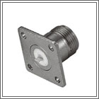
Element_115: I've tried to remove the effects of the SMA connector by using "port extension" feature of the PNA-X network analyzer. These SMA connector look like
55_1231521778.jpg

To do the port extension I simply "cut out" the small soldering section and measure "open circuit". I was hoping this would calibrate out the effects of the SMA connector, since the manufacturer does not provide models for this type of things.

Does anyone know how to incoporate these connector into their EM simulation?

Biff44: I understand unity reflection coeff is never achievable in real life, but how close? Its good that you said 0.9 is not the best one could do. Whats the best you've seen with microstrip circuit of this type? Also, are these losses frequency dependent at all from your experience? Thanks
 

smith chart short circuit

I guess that you are building a matching network and also harmonic traps at the same time. At harmonic frequency it is close to short. I noticed that you are using magnitute of reflection. I think a better choice is S21 in dB. And another suggestion is that -30dB and -40dB in S21 is close. Maybe you don't need that accuracy.

Added after 1 minutes:

how to incoporate these connector into their EM simulation?
------You need 3D simulator
 

open circuit smith chart

y7wu said:
Hi all,

Class F PA requires the odd harmonics to be terminated with open circuit and even harmonics with short circuit in order to achieve square wave voltage and half sine-wave current which yields high drain efficiency.

In a gross sense, sure. But what about device parasitics? I think that you need to conjugately match out any device reactances at every harmonic frequency in addition to provided the open or short Real part impedance. Yes/no? If you do not cancel out the reactances, you will have the phases all wrong, and will not produce the desired square wave.

Practically, if you have little 50 ohm line between your matching structure and the connector where you are making the test, I would be happy with a 0.95 reflection coefficient magnitude.
 

Status
Not open for further replies.

Part and Inventory Search

Welcome to EDABoard.com

Sponsor

Back
Top