Continue to Site

Welcome to EDAboard.com

Welcome to our site! EDAboard.com is an international Electronics Discussion Forum focused on EDA software, circuits, schematics, books, theory, papers, asic, pld, 8051, DSP, Network, RF, Analog Design, PCB, Service Manuals... and a whole lot more! To participate you need to register. Registration is free. Click here to register now.

[SOLVED] How can NPN transistor be used as PNP ?

Status
Not open for further replies.

edmundopt

Newbie level 4
Joined
May 13, 2011
Messages
7
Helped
0
Reputation
0
Reaction score
0
Trophy points
1,281
Activity points
1,341
Hello all

this is my first post, hopefully in the correct section!

I've finish reading the book "Electronics for dummies", so only basic basic knowledge

I've visited this site and found this schematic
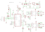
l297-l6203sch.png


The curious part about it is this :


PNP_NPN.png


I've simulate the circuit using Proteus Isis and it works , but I do not understand how, its a NPN transistor and it's being used as a PNP, is that a mistake, or it works on the real world ?


Also, using VCE = 40-12 = 28volts
It would mean that:
P = 28 volts * 0.5 amps = 14Watts, so it would get very very hot right ?
 

Re: NPN used as PNP math

It is not used as a PNP, it is using an emitter follower configuration, the output voltage is about 0.7v lower than the base voltage and that is why it is called an emitter follower, the emitter follows the voltage of the base minus Vbe which is about 0.7v.
Yes this works fine in the real world and you are correct that the transistor will get very hot in this case because the input is 40v and the output 12v (the output will actually be close to 11.3v)

Your first schematic is a stepper motor driver, it doesn't include the described transistor driving the lamp.

Alex
 
Re: NPN used as PNP math

The pass device in this regulator is made up of an NPN in standard regulator topology. In this circuit, the zener diode is used to stabilize the base voltage of the NPN transistor, which carries the load current. The base-emitter junction behaves like a diode. In this way in the emitter we find Ue=Uz-0.7V. (A base current Ib flows only when the voltage Vbe across the base-emitter junction is 0.7V or more)
The load transistor is in series with the load, which is why this circuit is also known as a series stabilizer. The small base current Ib controls the large collector current Ic.
The emitter current Ie = Ic + Ib, but Ic is much larger than Ib, so roughly Ie = Ic.
The dissipation of the transistor increases only when the actual load current increases.
Yes, power on transistor P= Uce x Ic:grin:
 
Re: NPN used as PNP math

Thank you for the reply

The lamp is just used as a load example.

I've read a lot about calculations for transistors saturation(as switches) but did not know this "emitter follower", any good tutorial?

Is the Dissipation formula P = V * I correct for this operating mode ?

If so, is this really a bad circuit idea, or it requires a major heat sink?
 
Last edited:

Re: NPN used as PNP math

Note that in the shown circuit the base current will be less than (40-12)/12k which is 2ma, this current is not enough to output 0.5A so you will have an additional voltage drop, you will get less than 5v for the lamp.

Alex

---------- Post added at 10:27 ---------- Previous post was at 10:20 ----------

Is the Dissipation formula P = V * I correct for this operating mode ?

The dissipation formula is always the same , the voltage drop across the device multiplied with the current that goes through it.

If so, is this really a bad circuit idea, or it requires a major heat sink?

This is not a configuration disadvantage , you have used a high input voltage and you are want a low output voltage so the transistor heats because it has to drop the additional volts.
Even if you use a linear regulator to do the same you will have the same amount of heat, the only solution that wouldn't produce that amount of heat would be a pulse regulator.

Alex
 
Re: NPN used as PNP math

maybe it's 1200(1k2) resistor, and not the 12000(12k) .. Anyway, the zener will need to have a Izt > 23mA so probably 2watts zener, and the resistor will need to be 1watt, and the TIP41C will blow :) , what a great schematic :grin:


I'm using the following circuit for 44v to 5v :

44v 5v.png

But yes, the ideal will be PWM, but so far I have not enough knowledge to do that!
 

Re: NPN used as PNP math

You don't need to learn about PWM, a switching regulator with just a few components can do the job for you

**broken link removed**

Alex
 
  • Like
Reactions: edmundopt

    V

    Points: 2
    Helpful Answer Positive Rating

    edmundopt

    Points: 2
    Helpful Answer Positive Rating
Re: NPN used as PNP math

Yes, in Portugal, the only one I can buy is the LM2575T-ADJ, can't find the HV version, and it has two problems that I can't solve(maybe more studying):

1) Supply voltage: 40volts,45v maximum , so it requires some stable way of 44v->40v

2) I still don't know how to calculate how much it will heat , I think the only way is with spice models!
 

Status
Not open for further replies.

Part and Inventory Search

Welcome to EDABoard.com

Sponsor

Back
Top