Continue to Site

Welcome to EDAboard.com

Welcome to our site! EDAboard.com is an international Electronics Discussion Forum focused on EDA software, circuits, schematics, books, theory, papers, asic, pld, 8051, DSP, Network, RF, Analog Design, PCB, Service Manuals... and a whole lot more! To participate you need to register. Registration is free. Click here to register now.

[SOLVED] How can I simulate Capacitor Characteristics?

Status
Not open for further replies.

hannover90

Member level 4
Joined
Dec 8, 2009
Messages
70
Helped
0
Reputation
0
Reaction score
0
Trophy points
1,286
Location
Germany
Activity points
1,784
Hello all,

I want to simulate, the characteristics of a capacitor using cadence, but I don't know how can I start.

I used to simulate circuits by tran and dc analyses.

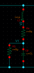
For capacitor characteristics, I try to do sp-analyse as follows:

S-Parameter Analysis --> Ports ----> /C0

Sweep Variable ----> Frequency

Sweep range ---> Start-Stop ---> 1 ... 10M

---> OK

I would be thankfull for answering the following questions:

Is it correct way? If not, what schould I do?
How can I define outputs for plotting?
How can I use zm of calculation?

Many thanks in advanced.
 

Attachments

  • Capacitor.png
    Capacitor.png
    3.6 KB · Views: 80

I would inject a unit (1A) ac current (i), run an ac analysis and (log) plot the resulting ac voltage (v) vs. frequency. You directly get (log) zm=v/i with i=1.

kV ≙ kΩ ; MV ≙ MΩ
 
Simple s-parameter simulation is sufficient.Connect your C model in series between two ports and do your simulation between the frequencies which you're interested in.
Zm1 or Zm2 will give you impedance vs. frequency of the capacitor.
 
Constant current sweep will give the voltage proportional to impedance.

Most people use a simple model similar to yours with only 1 capacitance and only a series resonant frequency (SRF) which is often just called the "Self-Resonant-Frequency.

But in ceramic multilayer structures there is a series and parallel capacitance (that may be nearly equal) and half of the simple (Cs only) model leading to a Parallel resonant frequency (PRF) which are recursive on all harmonics when horizontal to the circuit board.

However Johanson Technology Caps. ( and others) discovered that when the ceramic cap is mounted or created vertically, all the odd PRF frequencies are nulled out including the 1st.

Beware that not all Cap suppliers use the same SPICE model and so Ls will vary with model as well as Cp may be missing and lumped into Cs.

I believe this is the best model as it is accurate at both low and high frequency. ( below and above SRF)
Cequiv.png


So in recap. ( pun intended) first you get series resonance or lowest impedance at SRF, ( which should be above your main application) followed by PRF or open circuit at recursive PRF's, depending on the number of layers among other things.


EDIT:

Often it is not possible to find SRF above your operating frequency, so PRF and SRF must be characterized and effects noted when used with a variety of larger and smaller caps decades apart in the smallest size you can handle (e.g. 603 402 201) SRF and PRF will move. Stacked smaller caps are sometimes used. Not all suppliers are created equal and verification on SA+gen or NA is essential.

The best way to simulate RF Caps is to get the S parameter file from the supplier.
 
Status
Not open for further replies.

Similar threads

Part and Inventory Search

Welcome to EDABoard.com

Sponsor

Back
Top