Continue to Site

Welcome to EDAboard.com

Welcome to our site! EDAboard.com is an international Electronics Discussion Forum focused on EDA software, circuits, schematics, books, theory, papers, asic, pld, 8051, DSP, Network, RF, Analog Design, PCB, Service Manuals... and a whole lot more! To participate you need to register. Registration is free. Click here to register now.

How can i make a PCB at home ?????

Status
Not open for further replies.
modifying inkjet printer pcb

Pulsar https://www.pulsarprofx.com/ makes a transfer paper and foil system that works very well. I have made about a half dozen boards with their system and had good results.

The system uses a foil to cover the toner. This helps prevent pin holes and in general makes the artwork hold up better during etching. They have several interesting tips on there site including how to set the iron temperature, how to simulate a laminator using a wood dowel, and how to etch 1/2 copper boards in about 2 minutes.

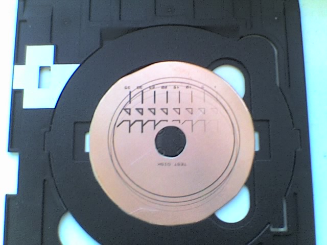
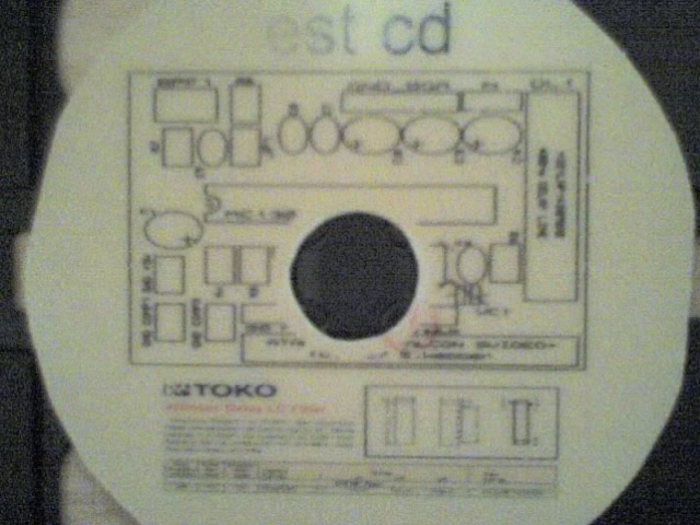
This is the first board I did with the system. Since then I have made denser and DS boards. The cost is less then $0.25 per square inch.

Most of the traces are .024 inches. you can see a bit of .016 in at least one spot. IIRC the smallest line on the lower left is .01 inches.
**broken link removed**
 
Last edited by a moderator:

how to make light up circuit board jewellery

nice board and good stuff at their site.
 

making a pcb at home copier machine

Method with laser print toner transfer can be realized with cheap 20€ Peach PL703 A4 Home Office Laminator or any other cheap type. PCB must be printed on thin glossy paper for advertisement brochures or simply on sheet of advertisement like that from Spar or Hoefer (Europe). Paper weight is about 56g/m^2. Laminator temperature is about 120°C and is usually high enough for toner transfer. Laminator is used here of cause instead of an iron. 1.6mm thick PCB can be used with no problems. Double-sided PCB is also possible.
Depending on toner or printer type it is necessary to use more than one pass through laminator or laminator temperature should be raised to max. 200°C. For this modification a bi-metal thermostat must be replaced. Thermostat from electric iron can be used.
After transfer you simply emerge PCB into water, paper get soft and after 5' you can remove it.
Results are as good as with photo method and Ink-Jet print on translucency foil. Traces width of 5mils can be realized with no problems. Copper pours are almost without errors.
Time for preparation of PCB for etching is less than 10'.
This is all I can show at the moment. Upper picture taken with flash and second with natural light. Thinnest tracks are 5mils, next 10mils and widest 40mils.
 

pulsar pcb laminator review

Here is the best method:

**broken link removed**
 
Last edited by a moderator:

epson direct pcb

Excellent link and material, however I would be careful in declaring anything as best, to me best would be the one that suits my needs.
What is best for me may not be best for others.
Its an excellent project but certainly not for newbies....
:D
 
pcb tank

hi all
after reading this topic in depth

as a hobby grade guy for home made pcb's
{if i need bigger than A5 i get it made for me roller tined resist thru plate etc..}


ignore the bit about snapping off the wings !!!!!!!

instead see the last post for me ill add the one i took off back as a hinge


so looking around i found several multi format printers epson stood out
using water and smudge proof inks by default
some scan copy etc also

and i hate to take apart and hack someone's hard work to build a printer
and prob get pay'd very little to do so

its just also a waist of a printer

i just bought an RX 560 epson photo printer

it has also a cd tray for printing any size or shape cd's
{they can be round or business card shape}

so looking at the way it senses the cd i realised i can just hack the cd tray
to make it A5 size and a stoppable {print area + a stopper plate}
as all the printer does is detect the edges of the cd placed in its print tray

making it square A5 is a breeze

i get the same results {better} than all the micro controller type addins
that put some people off this method

so for hobby grade any size up to A5
{+1" all round at least.... a3 epson's have an A4 size cd print tray}

can be printed better and on standard resin or glass fibre board
and double sided is less hassle
no need of a jig or alignment or guesstimated electronics counters etc

and you can scan direct to the board with or without a computer connected !!!!!!!
so copying a board is easier {i have a few old baked amp pcbs to remake}

so. conceder what i said here before you destroy a good printer

the Rx560 i got from pc world online for £99.99 reserve and collect service

if you walk into the store it costs £129.99 {a cheek of them}

the Rx 560 for me was the best choice and had nice reviews
there next model up 640?? just uses different inks and has bad reviews

has exactly the same features except it has a 1200dpi scanner
and not 3200dpi like the 640
{i can live with that }
as 600dpi is all that's needed for copying boards for sure
{im not into theft of pcb design}

just in repairing old wide tracks amps not to tightly tracked
@1200dpi scanner is fine
the print resolution is exactly the same @ ~1500 dpi y axis

I've modified the tray
and it worked first time

quick cure in the oven 120deg c door open preheat and sit the printed pcb in for 10 -15 min's {door open }

and i got a perfect replica from a scanned pcb even the silk screen
{remove the brown using print shop pro}

i used etchant for press and peal
maplin 1kg 10quid when it get saturated add a cap full of thin bleach then electrolysis to remove most of the copper
use copper nails as electrodes and a 9vdc source
will make it last five times longer

add cement dust and half a cup of water to it stir and let it go hard
then throw it in the rubbish as its now inert
when its expended and tired out
then printed a full colour silk screen to the fresh pcb


im very pleased
and thanks much to the original poster's


^^^^^^^^^^^^^^^^^^^^^^^^^^^^^^

:D !


this method for me works far far better than press and peal foil
or even uv exposure!!!!!!
I've tired them all and this is by far the easiest pcb I've ever made
except for a screening plate

********************************************************
to modify the tray
when i got it opened up and installed and plugged in etc ink added
as per its easy start pages
{ps you don't need a usb cable pc world try to ram one at you anyway}

the cd tray comes as a 2mm thick cd plastic tray
that slides in and out the buffer rollers and print head
and so another family of cd roms types can be sold
the cd's have to be 1.25mm types with a white label
{this is just so you can see the image it draws etc}

and be level with the tray top surface to protect the print heads

or can be silver ones but double resin again slim ones ... so called printable

however


to modify it for pcbs
i simply cut a rectangle using a key saw very carefully
then squared it with a needle file set and ween stones

the rectangle i used is 12 X 16 cm {cd is 12X12}
start from the back rim of the cd {the bit that goes in first}
to 4cm past the front rim
it worked up to here without any problem past this i don't know

ill add to this
i need to cut a slot in the back of the chassis so it slides back more and mount the end detector sensor up to 3" back
{in this its a separate sensor.. handy}

the rollers/heads pressure assembly goes up with a light pressure 7mm - 20mm
so i made a single pcb layer {1.75mm-2mm types}
i used glass fibre board and cut it to have the same dimensions
as the tray with also a rectangle to make the tray deeper

the rest is a tube pair of epoxy resin easy apply
and some g clamps and spreader bars to set it up

as the print head pressure roller assembly goes up so far and locks easily at 5mm
i see no probs up to maybe 10mm total table depth

it still runs with no resistance or damage at 5-7mm so its for me
and the pcb sits at the right height +1X a thin pcb .5mm or .75 types
this way you can just put a standard one in and a thin on top or a thin one in the base to pad up the thick one

under this i used a thin pcb layer as the bottom cover
just a flat pcb piece with the same slots cut in it as the master above

and made some right angles for various sizes of board as stoppers
im in the middle of making some oblong stoppers
then you spray them with black car paint or use a big permanent ink marker on the coppers
these are used to fix the board in position

it slides in and prints very sweet
with no damage

oops i broke my cd tray
spare parts
easy buy a few etc..
to make cd's

i like this it worked !

forgot to add

you need to also modify the cd tray acceptor rails on the front cover
by taking there tops off with {eeeeek} flat pliers and file them and ween stone
and just using them as a sliders instead
this way you can feed any depth tray up to i suppose 6 mm without problems over time {except spring wear ???? }

it goes without saying ill make efforts to modify the case to accept A4 trays as long as its not invasive on its normal functions

this should be the rule

otherwise i feel sorry for the person who built it in the first place

and for the plastic heap from the old case ... bo ho

its worth pointing out
this also invalidates the warranty of your printer

ps.... put the pcb board on a board on the wall
and Polish it with chrome cleaner and a dolly pad on a drill till it gleams

then clean with acetone

use ground planes always
assures print quality
fast etch with lower copper dissolve so extends the life of etchant fluids


the upper pressure assembly of the print rollers set
is flexible its height is the height of the print head

it goes up at least 20mm as long as the printer locks for print
your laughing

but becarefull above 7mm I've not tested it past 5
{hum yet im loath to its only plastic it works}
so i don't see any jam ups for multi layers thicker sets being a problem
two thin one thick etc
height is all that matters
as long as the tray table is flat on top shinny copper etc


cool
the happiest day of my armature electronics efforts

ill post some pics when i get my phone software to work hey

i can scan some

ill do a hot off the press utube video or something
 

make pcb milling with printer

VSMVDD said:
hi all


after reading this topic in depth

as a hobby grade guy for home made pcb's
{if i need bigger than A5 i get it made for me roller tin'd resist thru plate etc...}


so looking around i found several multi format printers epson stood out
using water and smudge proof inks by default
some scan copy etc also

..............

GREAT!!!!!!!!!
Do you have a Picture?

Thanks
 

silver ink pcb

salt little moisture mix is best to clean the inks off i found {much like gums}
pictures ill work on my phone needs software ill need to find
but i have stages of design and progress snaps
motorola never make anything easy...
brilient phone
no flash card or direct usb access

go look at the same printer in the store with what ive written in mind

then youll buy it for sure

the brochure is on epsons site with full docs RX560 orRX640 {i got the 560}
i havent even stripped the printer down
or even taken a screw out it just snapped off the guide wings


using a torch i see its easy to print A4 upto 20cm deep for sure !!!!!
this is definatly the printer to aquire !!!
there seems to be just an end stop for the print head as a thru sensor
only needed in cd print mode maybe a mixed mode can be used or that cd mode is enought with rim end senor detection as paper uses anyway
the other two thumb shaped slots of the tray
are just for lifting out the small disk shape inlay template that comes with the tray


the only end stop to full A4 seems to be the slot in the back thru the plastic molds
i see no obtrusions { ill strip it down and report on this for sure}

and also the slider on the font tray paper/cd sloped handler
 

overhead projector pcb

Wow!

I didn't check replies long time ago ...

Really great work, and fantastic replies!

I looked around yahoo groups, and found a usefull PCB related group..

**broken link removed**
May be usefull to guys whom are interetsed in PCB design..

I'm now OFF PCB! I am working in IC design instead :D

Thank you all for contribution, and go on!

Regards,
Ahmad,
 
Last edited by a moderator:

pcb etch resistant sticker

VSMVDD I assume that double-sided PCB production with your method is also possible. What are your experiences?
My appologies if you already mentioned it but reading your posts is like looking at some txt form algorithms and its hard to follow.
 

pcb+inkjet printer modifly

no problem .... 2 sides or multilayer {thin pcb} two sides each

here is the html docs from this printers manual
look in the folder html for basic -3 html

it tells you with some pitcures what it normaly does and normal cd requirements

ignore the bit about smears this only happens if you use extream saturation and black only seems unaffected

silk screen is fine thou
 

making pcb at home

as I've said in other places
=================
you can safely do 9mm
i stacked up 9mm of paper
about 40-80 sheets
a bundle and this rx560 didn't moan or grunt shutdown or blink
it just printed the top sheet and spat out the whole block
so 9mm seems fine {.9cm}
this is enough to do plenty thickness
and i didn't even stress the printer or force any sort of shutdown {not my remit}

no grrrr noises or bad things
...
also

i shaved the front of the tray bottom boards to a slope like the top
to easier load and ween sanded it
{fine rock sanders blocks from scotland for plastic and fine jewelry working}

i also made heaps of cutouts
pcb is cheep
so making cutout spacers as a set.. is a good idea
saves you looking for them for odd shape boards
also a few sets of shape types is cool
use a table jig saw or cnc and guide to cut them squared or visit one
you need this stage perfect
even use a cnc to make a new tray for you complete
cutting pcb is the most important i find for this so far
so far its been the most important thing
to have flat squared boards tray and spacers
the guide rail seems THE ONLY thing stopping this being A4 or A3 same family !!!!
so ill need to fashion some metal hinge as a holder
for a bigger plate made from pcb
hehehhehe

A4 here i come
seems after i really examined it with a strong light
i see NO obstruction as the A4 feed is flat from
the paper tray feed on the back when its rolled down to the pinch roller sets
and i lifted them to at least 8-9mm with ease + a little
also with the paper bundel as it was allgned the back rollers lifted

so its A4 till printed size or around about a bit less maybe
the printer is 414 mm depth back to front {from print head to back roller feed 200~}

so full A4 size pcb CAN be printed by changing the right tray guide rail position
to the far right side a new tray 2.5mm deep for protection
upto 5mm deep for safety
and over 9mm deep if you want to cause a problem { but keep it to less than 7}

so this is heeps of depth of tray .... nice 1

and some software
not sure what's needed yet
someone go buy this printer and throw in your effort
for sure it works ...further people are needed with extra thoughts
above all im more than happy so ... anything else is another gram
sooso..
no slots cutting needed for a4
the print head its self lifts up past 20mm but i recon a 10mm lock to print is what its tollerance is set at
i ordered two new trays also {15.99+post uk}
so i can make a new one from thiner pcb
ill use this time a rubber glue like evostick to allow flexing of the tray
{for A4 use also }
althought my 5mm deep one is fine i crave for a4 also
2.75mm deep

just cut the right guide rail off
and add a purpose made tray made from thin .5mm using rubber glue
fashioned pcb layers

i need a cnc machine!!!!


26_1173906730.gif


Added after 2 hours 21 minutes:

if you plan to use a cnc machine or fashion a new A4 style tray dont snap off the left most guide reuse it and lower it on the new tray to still be the base

66_1173913941.gif


tray made of 1 layer copper .5mm as base and 1.75mm upper
with layout for sensor a4 total depth 2.5mm table

order to epson cancelled

and i think ill add a very thin flat piano hinge
as a slider where the right slider was anyway

maybe later add another further right

Added after 2 hours 14 minutes:

ok

A4 tray made

sliding it in with the print head ass held up i can slide it back to the rollers all the way till about 160mm into the tray so i guess it will run into the rollers

looks good for a test

i made the tray stoppers using a bit of board 16 X 16
to see if the edge will travel past my test size and cd size by 4 cm
{cd is 12 cm dia}

Added after 3 hours 12 minutes:

some snaps of the first stages to make the A4 tray
i didnt really snap my guides off chuuu think im daft
eeek but ill need to soon alter the right one...
and add a hinge for small trays
these are the photos from yesterday afternoon
ive made the tray ill get back to it tomorrow
tired now

sleep for 8 hrs

had a brain wave as usual simple

ill cut a channel down the tray bottom pcb
and then reduce the rail to .5mm it will come thru the tray but this is little problem as the pcb has copper also

i notice to step off properly and retain height and level top
you can use double sided boards and roller solder or evostick rubber {kind of} tacky glue and roller it shut
after cuting the holes

the rest is finishing with files and a sander block set as described

at the far left of the tray is a little spike im sure this triggers the back sensor

so this will need fashioned and glued on using epoxy a few more
guides to mill than the tray has already.. for the greater width
i think would be best
ill measure it up and think more
as this part goes on
today was spent writing it up more work tomorrow

......................................<:D>..........................................
 

pcb etching .10mm tracks problem

You have to do alot of trial and error.
I have DIY a PCB board myself.
Got it done but not 100% perfect
compare to the commercial PCB.

Here's a step by step PCB making process,
for all those interest in fabricating on their own.
It is fun.....

**broken link removed**
 
Last edited by a moderator:

torch pcb remove

bo ho

here is the next set of photos
instead of running it ill do this in stages

here is the pcb print i just made today

i got a piece of .5mm {hard to find local ill need to travel into the city center}
i simply cut it into a disk shape for testing
worked like a charm first print
all files included {proteus design ,test files bmp and cd printer save file}
for the test i used some circles 1 5 10 15 th

there is a marked ledgend

i am waiting for it to dry {just done this}
and ill bake it in a few mins time
ive got the kettle on for some etchant

so now you tell me its a waist of my time !
....:D
ill post a nicer picture of the finished disk later
then ill make the tray i fist want to visit a cnc lab and draw up the new one
ill take this slowly and not ruch at it i want to improve
what i know with hard fact bit by bit

......

notice i left dileberate damage and a half clean surface
i want to see how it copes with this

20_1173982429.jpg

i reon ill bake it for 30 mins just to besure the first run and trim it as i go

ill update this file is 1/2 hr with the results
 

toner transfer sheet agent in sri lanka

well mixed news

although it prints fine the inks arent waterproof atleast the black isnt
so ill need to aquire some of the inks recommended above and perfect it further
atleast we know this for sure works
maybe i didnt dry it long enough???

i already tried it with a 16cm X12cm
it still prints it as long as your in manual print mode
so i guess vproor s..it results with this clara ink
roll on a few little bottles of ink please

maybe someone can post what inks they used ???

i only got etchant today but last nights is better unbaked
just a wipe test its fine
so perhaps i need to dry them overnight then cure then oven it also
like a pot !!!
here is a picture of the silk screen side just for fun
i think only the black ink needs changed out
and just use a fixer on the disk silks

oh full colour
sorry for the grainy image but my camera isnt too hot
the words test CD are gradiated
6_1173989280.jpg


**broken link removed**

site recons its "waterreistant" both pcb's washed pretty much
however at least its proved it will work fine

and onward and upward


well looking at this again at the good links above i see my issue
i need to bake its brains out over a hot ring till its grown and crusty {LOL:)
here we go again
but i did learn something
 
Last edited by a moderator:

drawing pcb on sheet iron

It is generally accepted that the ink required for direct inkjet printing will be a pigment based ink. The link that follows reveals that the Claria ink is a dye ink, albeit a robust one.

**broken link removed**

Check out **broken link removed**


Here you will find successes with MIS pro and Epson Ultrabright pigment inks.
 
Last edited by a moderator:

make a pcb from a copy machine

ill order a bottle of the black ultrachrome stuff
as its just black ill need
{i asked in the group{already found it}} for more data
see what comes back
:D
a few members mentioned about thru plated holes

to do this you use a cnc machine or a bench drill
and a drill map print out
print this to the pcb first in reverse video
so you mask the holes or to save inkjet ink

use an inky pen {wide RED or BLUE marker}
so the black shows and print this instead

then drill all the holes
then use an electroplate tray
{a 9v battery or look below for a design to use if your in production}
and copper sulphate solution

attacha soldered wire to a spare corner each side

dont forget to cover both electrodes so the contact point with the solution of atoms is at the hole and the solution isnt polerised in other ways


can you guess what it is yet ???

so then redrill it with a smaller size drill or dont its up to you
it will form a good enought hole
but usualy plate till the holes fill fully with copper

the use of cnc is better but youll get away with it

then just print on the design and process as above


bingo thru plates ....!!!


cheep to make electro plating device i made some years ago
the original design was for a car that makes some of its own fuel
pretty crude

however i discovered it made a VERY good
highly controllable ramping plater
for pcb work


youll also need a tray a pump for a fish tank for bubbles
and some copper sulphate and copper foil
and a battery {car is best or dc supply 12v}

some degree of over current is drawn becouse its a different solution to water...
unless you fit two 16 R resitors
{i used 10 watt ones but they only get slightly warm}
inline with the positive electrode feed

never got around to adding a limiter to the driver
did think then to move it to mcu but never got it past this

slow electrode for plating metal to metal
fast for plating to plate..


the copper foil is there to provide the solution with copper
and use the slow electrode connected to this also

otherwise you run out quick
you can make your own copper sulphate from copper dust
and {{new} water it down} car battery acid

{stand well back and dont do it inside or use a fume cupboard }

the application of a silver ink pen {conductive heavy one from circuit ive mentioned this one before in keyboard stuff}

round the rim of the hole
just to cover the copper hole inner rim {not on top of the hole}
quickens the plating process

usualy this whole step to fill the holes takes about 10 -15 mins
using the plater above this can ramp it to 5 -6 mins max for standard
glassfibre doublesided boards {1.75mm}

.5mm type takes a dip or two only 1-2 mins dip ramp {frizzle}
 

what cool thing can imake from a printer

Moa said:
It is generally accepted that the ink required for direct inkjet printing will be a pigment based ink. The link that follows reveals that the Claria ink is a dye ink, albeit a robust one.

**broken link removed**

Check out **broken link removed**


Here you will find successes with MIS pro and Epson Ultrabright pigment inks.


thanks for the direct info it gave me an idea
after reading about the polymer ink

i posted my proposed solution in the yahoo group
to the inkjet ink fixer problem

just use a fume cupboard stage and super glue and heat
to fix it like fingerprints and the dry ink will go hard

so any ink will work :idea: :D for sure and go hard
as they are oil & polymer based and polymers are oil anyway

so a drying stage is all thats needed

then fume them

.....


my old tube of super glue has gone hard
ill get a little bottle from the shop tomorrow


fume maker {soldering iron }

put it a big stoaway plastic box drip a drip of glue on to its tip
close the box lid and turn it on for 10 mins till the cloads clear
the box also soaks up the fumes

and will go black inside after a while of uses

ill try this next before parting with cash for ink

yawn.... tomorrow is another day....

..... :arrow: bed
 
Last edited by a moderator:

ho to make pcb

I know there is already a pretty exhaustive list, but I figured one more wouldn't hurt. I use the laser printer method with Staples brand glossy paper and Muriatic Acid(HCL) + Hydrogen Peroxide(H2O2) as echant.

Method:
Print with the highest ink settings the printer will allow (I print in 300 dpi to keep it consistent with the board)
Now remove any rust/bumps with steel wool. Then clean with acetone and a paper towel. (don't mix steel wool and acetone)
Then take a household iron, and iron with a lot of pressure on the hottest setting for 3-5 minutes. When you're satisfied, drop it into some water. (warm/hot water is best)
Let it soak in the water until you see the paper start to come off, then rub it with your fingers / an eraser / a toothbrush. Once ALL the paper is off, you should have a board with very nice traces.
Mix the Acid with peroxide 1:3 (3 peroxides), and drop the board in. (be careful with the acid, it burns everything)


Recently I got a laser printer that was being thrown out because the rollers didn't feed paper correctly.
I remembered an article and decided to make one of these: hxxp://www.storm.ca/~rheslip/pcbfuser.htm
This would eliminate the ironing step, and make double-sided PCB's easier.
I am still confused about his circuit as he did not explain it very well,
but I will test what I THINK he meant, and hopefully that woirks.

This method is cheap and has worked great for me. If anyone needs more info or specifics, feel free to PM me.

~Spork
 

Status
Not open for further replies.

Part and Inventory Search

Welcome to EDABoard.com

Sponsor

Back
Top