Welcome to our site! EDAboard.com is an international Electronics Discussion Forum focused on EDA software, circuits, schematics, books, theory, papers, asic, pld, 8051, DSP, Network, RF, Analog Design, PCB, Service Manuals... and a whole lot more! To participate you need to register. Registration is free. Click here to register now.
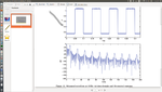
The 10Hz clock has a lot of noise with x5 clock divider noise so there are 10 sidebands between each odd harmonic. Could be some 50Hz noise injected from long wires. modulating the phase.
YOu can play with this generator and adjust the Fourier response with mouse or time scale or choose from menu any wave..
turn on sound... enable mag/phase, log scale .. change Nth harmonic up to 19, vary frequency... e.g. 10Hz sq wave.
The WAY that I look at spectral density of a square wave is to compare the odd with the even. These look to be 40db down and same as the other noise inbetween so the slew rate is symmetrical and the duty cycle must be much better than 1% error or 40 dB down and probably is almost perfect since the rise time to pulse width ratio is probably 1e6 and it came from a symmetrical CMOS /2 flipflop or counter.
Note there are 8 lobes between 50 and 150 Hz suggesting sub harmonics or sidebands from other counter current in the divider producing more clocks in the counter. Isolating the ripple in PS or crosstalk can clean this up even more>
FWIW whoever took this photo had sources of subharmonic clock noise
The other random noise will likely be due to the flat top power supply noise or signal noise added to signal which adds phase noise.
This site uses cookies to help personalise content, tailor your experience and to keep you logged in if you register.
By continuing to use this site, you are consenting to our use of cookies.