Continue to Site

Welcome to EDAboard.com

Welcome to our site! EDAboard.com is an international Electronics Discussion Forum focused on EDA software, circuits, schematics, books, theory, papers, asic, pld, 8051, DSP, Network, RF, Analog Design, PCB, Service Manuals... and a whole lot more! To participate you need to register. Registration is free. Click here to register now.

How can I get rid of the relay in this schematics ?

Status
Not open for further replies.

expert_vision

Junior Member level 3
Joined
Dec 5, 2012
Messages
26
Helped
3
Reputation
6
Reaction score
3
Trophy points
1,283
Visit site
Activity points
1,506
I've made a simple Ni-Cd USB charger that uses a relay to control when power is applied to the current source (Q1+Q2+R5). Is there a way to use a cheap semiconductor solution to replace the relay without affecting the circuit's current behavior ?

What the circuit does is this:
- battery is inserted in the charger
- because battery voltage is below ~1.38V the relay goes on and battery is charged at 160mA
- when voltage applied on the battery reaches ~1.44V, the relay goes off, and the battery drops to about 1.4V
- charger won't start again until battery goes below 1.38V

I know I could use a transistor instead of the relay, but that would would not switch the current in a on-off way, and it would rather slowly drop the current as the battery voltage approaches 1.44.
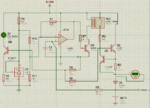
Ni-Cd charger.GIF
 

A P channel FET should work fine as a substitute. Since it's being controlled by a comparator with hysteresis, it should function well as a switch, and current shouldn't vary any more than with a relay.
 

Yes, but wouldn't that P-FET be slowly closed by the OA in such way that the voltage applied by the current source to the battery doesn't exceed the reference voltage from the non-inverted input. This is gonna result in a slowly decreasing current being injected in the cell. What I would like to achieve is a immediate shutdown when 1.44V are reached.
 

The op amp is configured as a comparator with hysteresis, so its output can either by saturated high or low. Therefore the gate of the FET can only be high or low, making it functionally a switch. As far as I can tell, there's nothing about a P FET which could cause the current source to be anything other than zero or the limit.
 

The OA is indeed configured as a comparator with hysteresis, but there is also a loop/feedback coming from the current source to the inverting input, and the current source is controlledby the OA, which makes the OA to adjust it's output so that the inputs are equal. I tested it with a transistor as u mentioned and the OA does slowly drop it's output. The digitization is done by the relay which can't have it's resistance set to anything between ~0ohm and ~infinite.
 

The OA is indeed configured as a comparator with hysteresis, but there is also a loop/feedback coming from the current source to the inverting input
The only feedback is from the battery voltage, which shouldn't change significantly depending on its instantaneous current (NiCd usually has very low ESR). Its voltage should be dependent on its charge.
and the current source is controlledby the OA, which makes the OA to adjust it's output so that the inputs are equal.
The op amp is configured as a comparator, its output should only have two states, on and off, and thus so will the PFET. This is regardless of feedback to the inverting input (so long as the feedback to the noninverting input is greater, which should always be the case).
I tested it with a transistor as u mentioned and the OA does slowly drop it's output. The digitization is done by the relay which can't have it's resistance set to anything between ~0ohm and ~infinite.
If you're observing this, then that means you've built the circuit different from the schematic. Or you're actually observing fast transitions on the output which average out and appear to be slow.
 

The voltage applied on the cell by the current source can go pretty high to maintain 160mA, and as the cell gets charged it gets more and more resistive to reverse polarization. In fact I measured as much as 1.5V when cell is fully charged. I'm stopping at 1.44V. Here is what happens when voltage applied by the current source gets close to 1.44V: as it approaches 1.44V, the difference between the inverting and the non-inverting input gets very close to each other. So, if the current source is trying to apply more than 1.44V, the OA drops the voltage enough to make the current source not exceed 1.44V, so the amperage gonna start to drop very slowly as the battery gets more and more resistive.
 

Okay, I'm surprised that the ESR of the battery is high enough to cause a voltage change of more than a few mV. But even so, you should never observe the output of the comparator/op amp being anything other than 0V or 5V (same for the gate of the PFET), except for the very brief switching times. Even in the case where the current feeds back to the error amplifier. What should happen is the circuit will form a relaxation oscillator, whose behavior will be related to various circuit parameters (ESR of the battery, battery charge, output current, comparator hysteresis, time constant of the feedback, etc). This is not necessarily a bad thing. The PFET is still acting like a good switch, but it may be toggled very fast, meaning the average output current will drop. But even it's still a switch.

How are you observing this behavior? An oscilloscope, or a DMM?
 

I use DMM. I don't have an oscilloscope, unfortunately. You might have a point, maybe I should increase the resistor between the battery and the inverting input to increase the the delay made by the capacitor to get that relaxation oscillator behavior.
 

Slowing down the oscillation will probably reveal the changing output. So yes, increasing the RC time constant, or increasing the comparator hysteresis will slow it down. The oscillation will occur so long as the battery voltage ripple (determined by Iout*ESR) is greater than the hysteresis. So by changing around some circuit parameters it should be possible to eliminate the oscillation entirely.
 

Status
Not open for further replies.

Part and Inventory Search

Welcome to EDABoard.com

Sponsor

Back
Top