generator*****
Newbie level 4
ic 7107 as dvm
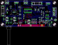
hi friends I want to make this soldering ıron but I don't how to adjust it.language of document about this iron is in Hungary unfortunately I don't know Hungary . can anybody help me

 [/img]
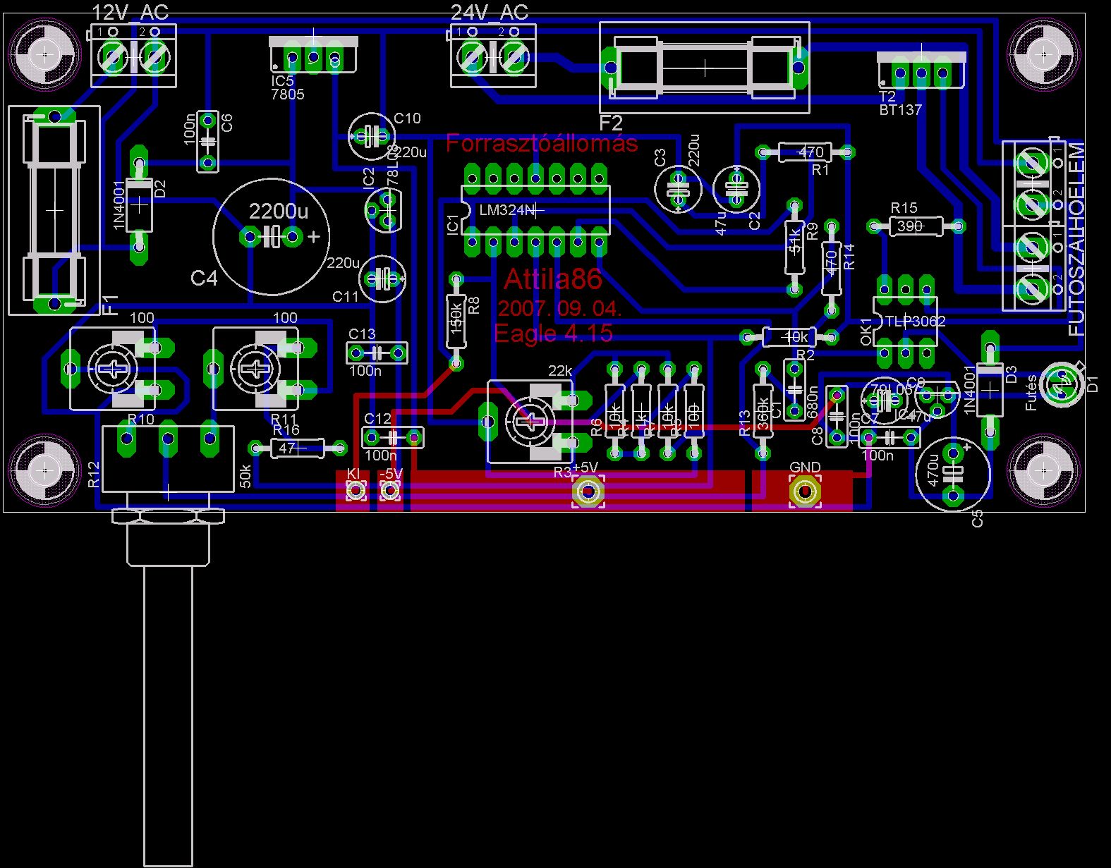
and this is the original page of this project
www.freeweb.hu/pa-elektronika/forrasztoallmas.htm
hi friends I want to make this soldering ıron but I don't how to adjust it.language of document about this iron is in Hungary unfortunately I don't know Hungary
. can anybody help me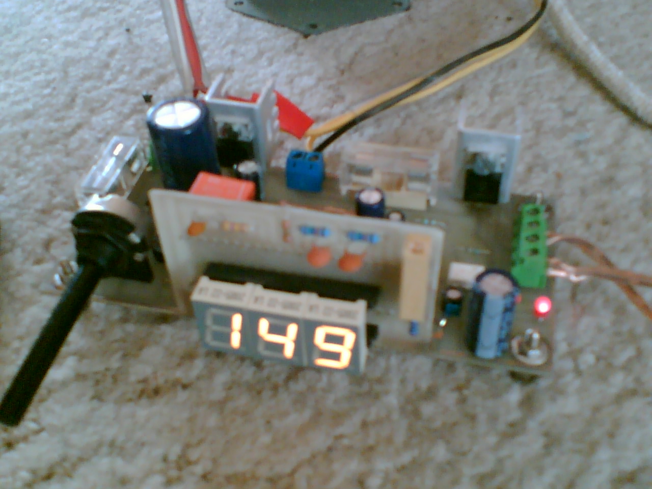
 [/img]
and this is the original page of this project
www.freeweb.hu/pa-elektronika/forrasztoallmas.htm