Continue to Site

Welcome to EDAboard.com

Welcome to our site! EDAboard.com is an international Electronics Discussion Forum focused on EDA software, circuits, schematics, books, theory, papers, asic, pld, 8051, DSP, Network, RF, Analog Design, PCB, Service Manuals... and a whole lot more! To participate you need to register. Registration is free. Click here to register now.

Homebrew tube lighting counter

Status
Not open for further replies.

neazoi

Advanced Member level 6
Joined
Jan 5, 2008
Messages
4,119
Helped
13
Reputation
26
Reaction score
15
Trophy points
1,318
Location
Greece
Activity points
36,918
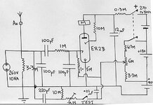
Hi I have seen this tube lighting counter https://volcaniclightning.tripod.com/aflashof.htm and I like it.

However the tube is a bit expensive so I searched for what can be made with the 5727 (2d21) as I have plenty of these.
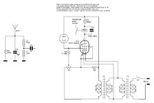
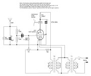
I saw a self-rectifying, self reset circuit attached in the datasheet (page 4).

I wonder how could the input circuit be transformed from the light detector to the antenna-based? Maybe a parallel tunable circuit centered around 1mhz should have sufficient reactance to peak the QRN pulse to trigger the thyratron? But then, how should I connect the parallel tuned circuit in this self-rectifying configuration, where there is no ground? This is what I wonder.
Just directly replace the phototube with this LC?

Also if you have any other such tube circuits to share, please let me know.
 

Attachments

  • 5727.pdf
    685.8 KB · Views: 218
  • lgctr.jpg
    lgctr.jpg
    28.4 KB · Views: 193

This is a redrawn representation of the circuit in page 4 of the datasheet.
I do not understand how the circuit works, anyway.

So I would like to see if I can attach the left circuit in it for RF, but I do not know where to connect the ground for that circuit, as the thyratron circuit is self rectifying.
Should I connect the ground directly to the cathode?
Should I connect it to the chassis (mains) ground?
 

Attachments

  • mycircuit1.JPG
    mycircuit1.JPG
    57.6 KB · Views: 191

The properties of a Thyratron are high current capability (hence being able to drive the mechanical counter) and a snap-action turn on point. They are not normal tubes, they contain a gas rather like a neon lamp, and if held just below trigger voltage between the closely spaced control grid and cathode, basically do nothing. As soon a the grid-cathode space ionizes, the whole tube becomes highly conductive so your input ground should be the cathode pin. One thing that looks wrong is the placement of the capacitor C1, normally it would go from the bottom of the 300K resistor to the cathode, the idea being that it charges slowly through the resistor and dumps the charge through the counter as the tube conducts, otherwise the current would stay on when triggered and the counter would be permanently energized. The potentiometer is to pre-set the grid voltage just below trigger point so it is as sensitive as possible and any additional 'spike' from a lightning discharge pushes it over the edge into conduction.

Brian.
 

    neazoi

    Points: 2
    Helpful Answer Positive Rating
The properties of a Thyratron are high current capability (hence being able to drive the mechanical counter) and a snap-action turn on point. They are not normal tubes, they contain a gas rather like a neon lamp, and if held just below trigger voltage between the closely spaced control grid and cathode, basically do nothing. As soon a the grid-cathode space ionizes, the whole tube becomes highly conductive so your input ground should be the cathode pin. One thing that looks wrong is the placement of the capacitor C1, normally it would go from the bottom of the 300K resistor to the cathode, the idea being that it charges slowly through the resistor and dumps the charge through the counter as the tube conducts, otherwise the current would stay on when triggered and the counter would be permanently energized. The potentiometer is to pre-set the grid voltage just below trigger point so it is as sensitive as possible and any additional 'spike' from a lightning discharge pushes it over the edge into conduction.

Brian.
Like this Brian?
If so, estimation of R1, R2, R3 values?

Note that the circuit is self-rectified it works only in the positive cycle of the mains power. So I am not sure about the C1 position. Datasheet connects it across the relay, but it has it there with dotted lines.
I think it is the negative cycle of the AC mains, that switches off the tube (read paragraph just below the image in the datasheet) and not the C1. I think C1 is there to delay the fast retriggering of the relay (cause the tube is really fast).

Most important for me is if this is the correct way to connect the RF circuit, and estimation of the values of the resistors (starting values to experiment with).
 

Attachments

  • mycircuit2.JPG
    mycircuit2.JPG
    68.7 KB · Views: 205
Last edited:

Running it on AC is certainly unconventional but yes, it will work as a diode. The drawback to using AC is the conduction will only be a little shorter than one half AC cycle at most so the counter will have to react very quickly. If you use DC, you can utilize the discharge of the capacitor to provide a higher current pulse and it will last longer.

The RF connection is fine, the input is voltage triggered regardless of the frequency so most important is to keep the impedance high and not to have any leakage path that could drop the DC applied from the potentiometer. Depending on the antenna, you could possibly just connect it directly to C2 and leave the LC networks out completely. I would leave a resistor to ground to discharge static charges or the circuit may trigger randomly.

I would suggest 470K as the minimum potentiometer value or it will warm up with the high voltage across it. The problem with that configuration is the effective supply voltage comes from the potential divider formed of R1 and R2 so you have conflicting requirements of voltage vs dissipation in the pot.

Brian.
 

    neazoi

    Points: 2
    Helpful Answer Positive Rating
Running it on AC is certainly unconventional but yes, it will work as a diode. The drawback to using AC is the conduction will only be a little shorter than one half AC cycle at most so the counter will have to react very quickly. If you use DC, you can utilize the discharge of the capacitor to provide a higher current pulse and it will last longer.

The RF connection is fine, the input is voltage triggered regardless of the frequency so most important is to keep the impedance high and not to have any leakage path that could drop the DC applied from the potentiometer. Depending on the antenna, you could possibly just connect it directly to C2 and leave the LC networks out completely. I would leave a resistor to ground to discharge static charges or the circuit may trigger randomly.

I would suggest 470K as the minimum potentiometer value or it will warm up with the high voltage across it. The problem with that configuration is the effective supply voltage comes from the potential divider formed of R1 and R2 so you have conflicting requirements of voltage vs dissipation in the pot.

Brian.
Thank you very much Brian, all understood.
Can you please suggest me initial values to try for R2 and R3 as well (so as not to blow things up)?
 

very interesting project!
is that any subtitution for that tube because in my country no one have it
thank you!
 

I don't think small thyratrons have been made for maybe 50 years. There may still be a limited market for giant ones in industrial switching applications but they would be very unsuitable for this circuit.

Brian.
 

very interesting project!
is that any subtitution for that tube because in my country no one have it
thank you!
I have a huge lot of 2D21 if you are interested, let me know with private message. I have bought them in the past for building a vacuum tube synthesizer, one tube per key!
Of course this beast project was never completed...
 

Status
Not open for further replies.

Similar threads

Part and Inventory Search

Welcome to EDABoard.com

Sponsor

Back
Top