Continue to Site

Welcome to EDAboard.com

Welcome to our site! EDAboard.com is an international Electronics Discussion Forum focused on EDA software, circuits, schematics, books, theory, papers, asic, pld, 8051, DSP, Network, RF, Analog Design, PCB, Service Manuals... and a whole lot more! To participate you need to register. Registration is free. Click here to register now.

Home Security alarm project

Status
Not open for further replies.

kle0ps

Junior Member level 2
Joined
Nov 12, 2012
Messages
24
Helped
0
Reputation
0
Reaction score
0
Trophy points
1,281
Activity points
1,426
Hello
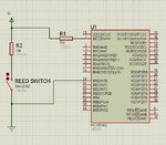
I got a assigment at my university which i must build a home security alarm. I use the microcontroller pic18f2520. I connect lcd on PORTA and keypad on PORTB and i want to connect contact magnetic on PORTC and i dont know how.
I bought this one:
**broken link removed**
Thats my code:
Code:
#include <p18f2520.h>
#pragma config WDT=OFF , OSC=INTIO67 , PWRT = ON, LVP=OFF, MCLRE = OFF
#include <delays.h>
// lcd code
//...
//...
//keypas code
//....
//...
void main (void)
{
ADCON1 = 0x7F;  //all IO are digital  or 0b01111111 in binary
TRISA = 0b00100000;	//sets PORTA 
PORTA = 0b00000000;	//turns off PORTA outputs       	
TRISB = 0b10001111; //sets PORTB bits 0-3 and 7 as inputs, 4-6 as outputs
PORTB = 0b00000000;    //turns off PORTB outputs
TRISC = 0b00000000;  //sets PORTC as outputs
PORTC = 0b00000000;    //turns off PORTC outputs
INTCON2bits.RBPU=0;
SetAddr (0x80);
WriteString("HELLO WORLD");

Does anyone help me how to connect the contact magnetic and with the code please?
Thank you
 
Last edited:

See this http://en.wikipedia.org/wiki/Reed_switch

A reed sw is like a spst switch, when magnel comes near it it switches ON. It is connected the same way as a switch is connected to microcontroller. You should make sure the current rating of the reed switch magnetic sensor. Can you post the datasheet of that sensor?

I send email to my seller and he will send me the datasheet in a week.

- - - Updated - - -

i have also problem with my lcd.
I upload this code to my pic:
Code:
        #include <p18f2520.h>
	#pragma config WDT=OFF , OSC=INTIO67 , PWRT = ON, LVP=OFF, MCLRE = OFF

	#include <delays.h>
	#define CLEAR_SCREEN  	0b00000001
	#define FOUR_BIT  		0b00101100
	#define LINES_5X7  		0b00111000
	#define CURSOR_BLINK  	0b00001111
	#define CURSOR_RIGHT  	0b00000110
	#define DATA_PORT	PORTA
	#define RS_PIN     	PORTAbits.RA6
	#define E_PIN      	PORTAbits.RA7
        void Delay20TCY()	//20 clock cycles, 2.5mS
        {
	Delay10TCYx(2);
        }

	void SetAddr(unsigned char DDaddr)
	{
	DATA_PORT &= 0xf0;                      // Write upper nibble
	DATA_PORT |= (((DDaddr | 0b10000000)>>4) & 0x0f);
	RS_PIN = 0;                   	// Set control bit
	Delay20TCY();
	E_PIN = 1;                      	// Clock the cmd and address in
	Delay20TCY();
	E_PIN = 0;
	DATA_PORT &= 0xf0;                      // Write lower nibble
	DATA_PORT |= (DDaddr&0x0f);
	Delay20TCY();
	E_PIN = 1;                      	// Clock the cmd and address in
	Delay20TCY();
	E_PIN = 0;
	}
	void WriteCmd(unsigned char cmd)
	{
	DATA_PORT &= 0xf0;
	DATA_PORT |= (cmd>>4)&0x0f;           
	RS_PIN = 0;          	// Set control signals for command
	Delay20TCY();
	E_PIN = 1;                      	// Clock command in
	Delay20TCY();
	E_PIN = 0;
	// Lower nibble interface
	DATA_PORT &= 0xf0;
	DATA_PORT |= cmd&0x0f;
	Delay20TCY();
	E_PIN = 1;                      	// Clock command in
	Delay20TCY();
	E_PIN = 0;
	}

	void WriteChar(char data)
	{
	DATA_PORT &= 0xf0;
	DATA_PORT |= ((data>>4)&0x0f);
	
	RS_PIN = 1;                     	// Set control bits
	Delay20TCY();
	E_PIN = 1;                      	// Clock nibble into LCD
	Delay20TCY();
	E_PIN = 0;


	DATA_PORT &= 0xf0;              // Lower nibble interface
	DATA_PORT |= (data&0x0f);
	Delay20TCY();
	E_PIN = 1;                      	// Clock nibble into LCD
	Delay20TCY();
	E_PIN = 0;
	}

	void WriteString(const rom char *buffer)    
	{		 
	while(*buffer)     		// Write data to LCD up to null
	{
	Delay20TCY();
	WriteChar( *buffer); 	// Write character to LCD
	buffer++;               	// Increment buffer
	}
	return;
	}       

	void main (void)
	{
	//SET UP
	// OSCCON defaults to 31kHz. So no need to alter it.
	ADCON1 = 0x7F;  //all IO are digital  or 0b01111111 in binary
	TRISA = 0b00100000;	//sets PORTA 
	PORTA = 0b00000000;	//turns off PORTA outputs    	
	TRISB = 0b01000000;	//sets PORTB as all outputs
	PORTB = 0b00000000;	//turns off PORTB outputs, good start position


	// this code configures the display   	
	WriteCmd ( 0x02 );				// sets 4bit operation
	WriteCmd ( FOUR_BIT & LINES_5X7 );	// sets 5x7 font and multiline operation.
	WriteCmd ( CURSOR_BLINK );			// blinks cursor
	WriteCmd ( CURSOR_RIGHT  );			// moves cursor right	
        SetAddr (0x83);
        WriteString("Hello World");
        while(1);	
        }

but my lcd show this message:
photo.JPG

Does anyone know why?
 

Finally i fixed my lcd. I connect the lcd with PORTB and its working fine.. i dont know why :/
 

Maybe your ADCON1 settings were wrong or you had not disabled the Comparators on PORTA. You have to set CMCON register if you have to use PORTA. Actually you have to disable Comparators.

You have to use
Code:
 ADCON1 = 0x0F;
CMCON = 0x07;
CVRCONbits.CVROE = 0;

Also try to use LATA registers instead of PORTA. LATx registers should be used instead of PORTx in PIC18.
 
Last edited:
  • Like
Reactions: kle0ps

    kle0ps

    Points: 2
    Helpful Answer Positive Rating
Maybe your ADCON1 settings were wrong or you had not disabled the Comparators on PORTA. You have to set CMCON register if you have to use PORTA. Actually you have to disable Comparators.

You have to use
Code:
 ADCON1 = 0x0F;
CMCON = 0x07;
CVRCONbits.CVROE = 0;

Also try to use LATA registers instead of PORTA. LATx registers should be used instead of PORTx in PIC18.

Thank you very much. It working now!:grin:
The problem it was with the comparators!

- - - Updated - - -

I have also another problem :-|
This is my new code:
Code:
#include <p18f2520.h>
#pragma config WDT=OFF , OSC=INTIO67 , PWRT = ON, LVP=OFF, MCLRE = OFF
#include <delays.h>
#define CLEAR_SCREEN  	0b00000001
#define FOUR_BIT  	0b00101100
#define LINES_5X7  	0b00111000
#define CURSOR_BLINK  	0b00001111
#define CURSOR_RIGHT  	0b00000110
#define DATA_PORT	PORTA
#define RS_PIN     	PORTAbits.RA6
#define E_PIN      	PORTAbits.RA7
void Delay20TCY()	//20 clock cycles, 2.5mS
{
Delay10TCYx(2);
}
void SetAddr(unsigned char DDaddr)
{
DATA_PORT &= 0xf0;                      // Write upper nibble
DATA_PORT |= (((DDaddr | 0b10000000)>>4) & 0x0f);
RS_PIN = 0;                   	// Set control bit
Delay20TCY();
E_PIN = 1;                      	// Clock the cmd and address in
Delay20TCY();
E_PIN = 0;
DATA_PORT &= 0xf0;                      // Write lower nibble
DATA_PORT |= (DDaddr&0x0f);
Delay20TCY();
E_PIN = 1;                      	// Clock the cmd and address in
Delay20TCY();
E_PIN = 0;
}
void WriteCmd(unsigned char cmd)
{
DATA_PORT &= 0xf0;
DATA_PORT |= (cmd>>4)&0x0f;           
RS_PIN = 0;          	// Set control signals for command
Delay20TCY();
E_PIN = 1;                      	// Clock command in
Delay20TCY();
E_PIN = 0;
// Lower nibble interface
DATA_PORT &= 0xf0;
DATA_PORT |= cmd&0x0f;
Delay20TCY();
E_PIN = 1;                      	// Clock command in
Delay20TCY();
E_PIN = 0;
}
void WriteChar(char data)
{
DATA_PORT &= 0xf0;
DATA_PORT |= ((data>>4)&0x0f);
RS_PIN = 1;                     	// Set control bits
Delay20TCY();
E_PIN = 1;                      	// Clock nibble into LCD
Delay20TCY();
E_PIN = 0;
DATA_PORT &= 0xf0;              // Lower nibble interface
DATA_PORT |= (data&0x0f);
Delay20TCY();
E_PIN = 1;                      	// Clock nibble into LCD
Delay20TCY();
E_PIN = 0;
}
void WriteString(const rom char *buffer)    
{		 
while(*buffer)     		// Write data to LCD up to null
{
Delay20TCY();
WriteChar( *buffer); 	// Write character to LCD
buffer++;               	// Increment buffer
}
return;
}       
void main (void)
{
//SET UP
// OSCCON defaults to 31kHz. So no need to alter it.
ADCON1 = 0x0F;
CMCON = 0x07;
CVRCONbits.CVROE = 0;
TRISA = 0b00100000;;	//sets PORTA 
PORTA = 0b00000000;	//turns off PORTA outputs    	
// this code configures the display   	
WriteCmd ( 0x02 );				// sets 4bit operation
WriteCmd ( FOUR_BIT & LINES_5X7 );	// sets 5x7 font and multiline operation.
WriteCmd ( CURSOR_BLINK );			// blinks cursor
WriteCmd ( CURSOR_RIGHT  );			// moves cursor right	
// Start of user program.   
SetAddr (0x80);
WriteString("Hello World");
Delay1KTCYx(8); //delay 1s
WriteCmd(CLEAR_SCREEN);
SetAddr (0xC0);
WriteString("Hello again");
while(1);  
}

When i test this, my lcd print only "ello again"istead of "Hello again" on a fist line instead of second line.
The "Hello World" print it only for 0.1 s
 

Your ADCON1 was also wrong. it should be ADCON1 = 0x0F;

See ADCON1 settings table in datasheet. The last line in the table makes all AN pins D i.e., digital i/o

Is "Hello World" displaying Properly?

Change this code

Code:
SetAddr (0xC0);
WriteString("Hello again");

to this code

Code:
SetAddr (0xC1);
WriteString("Hello again");

What is this

Code:
 TRISA = 0b00100000;;
make it
Code:
 TRISA = 0b00100000;

or
Code:
 TRISA = 0b00000000;;
if RA5 is not i/p but o/p.

I think you can use this circuit for connecting reed magnetic sensor. mention the max current it can handle DC/AC and also its working voltage 12V type or what
 

Attachments

  • reed sw.jpg
    reed sw.jpg
    229.3 KB · Views: 69
Last edited:
  • Like
Reactions: kle0ps

    kle0ps

    Points: 2
    Helpful Answer Positive Rating
Only with this code
Code:
// Start of user program.   
SetAddr (0xC0);
WriteString("Hello World");
is working fine.
I think the problem is with the delay, which is very quickly. Is only 0.1 instead of 1s

- - - Updated - - -

I change the TRISA = 0b00000000; and the Delay1KTCYx(100); which now it have delay 1 second but the second print is wrong again.
 

Are you getting"ello again" only in second line? If yes, Try to print "Hello World in 2nd line" if you get "ello World" then you lcd is damaged.
 

Yes i tried to print only "hello world" in the 2nd line and it print fine!
The problem is with the second print.
I tried and this code:
Code:
SetAddr (0x80);
WriteString("Hello World");
Delay1KTCYx(100);
WriteCmd(CLEAR_SCREEN);
SetAddr (0x81);
WriteString("Hello again");
but the second print is wrong again. It print "ello again" on the fist line
 

try this

Code:
SetAddr (0x80);
WriteString("Hello World");
Delay1KTCYx(100);
WriteCmd(CLEAR_SCREEN);
SetAddr (0x80);
WriteString("Hello again");
 

same "ello again" on line 1 and line 2? which compiler are you using?

try this

Code:
void WriteString(const char *buffer)    
{		 
	while(*buffer)     		// Write data to LCD up to null
	{
		Delay20TCY();
		WriteChar( *buffer); 	// Write character to LCD
		buffer++;               	// Increment buffer
	}
	return;
}


void WriteChar(char *data)
{
	DATA_PORT &= 0xf0;
	DATA_PORT |= ((data>>4)&0x0f);
	RS_PIN = 1;                     	// Set control bits
	Delay20TCY();
	E_PIN = 1;                      	// Clock nibble into LCD
	Delay20TCY();
	E_PIN = 0;
	DATA_PORT &= 0xf0;              // Lower nibble interface
	DATA_PORT |= (data&0x0f);
	Delay20TCY();
	E_PIN = 1;                      	// Clock nibble into LCD
	Delay20TCY();
	E_PIN = 0;
}
 
Last edited:

same "ello again" on line 1 and line 2? which compiler are you using?

try this

Code:
void WriteString(const char *buffer)    
{		 
	while(*buffer)     		// Write data to LCD up to null
	{
		Delay20TCY();
		WriteChar( *buffer); 	// Write character to LCD
		buffer++;               	// Increment buffer
	}
	return;
}


void WriteChar(char *data)
{
	DATA_PORT &= 0xf0;
	DATA_PORT |= ((data>>4)&0x0f);
	RS_PIN = 1;                     	// Set control bits
	Delay20TCY();
	E_PIN = 1;                      	// Clock nibble into LCD
	Delay20TCY();
	E_PIN = 0;
	DATA_PORT &= 0xf0;              // Lower nibble interface
	DATA_PORT |= (data&0x0f);
	Delay20TCY();
	E_PIN = 1;                      	// Clock nibble into LCD
	Delay20TCY();
	E_PIN = 0;
}
First it print ("Hello World") on fist line and after 1 second it print ("ello again") on fist line.
I use c18 compiler.
I tried your code but i have error to this line void WriteChar(char *data) i think is the *

- - - Updated - - -

Ps. This code it was for pic18f1220. i tried to this pic and it print correctly!
 

I will check the code.

Code:
 void WriteChar(char data);
is the prototype, then how can you use a pointer like
Code:
 WriteChar(*buffer)
?

What lcd are you using? Is it HD44780 Compatible? If not post the lcd datasheet.
 
Last edited:

I will check the code.

Code:
 void WriteChar(char data);
is the prototype, then how can you use a pointer like
Code:
 WriteChar(*buffer)
?

What lcd are you using? Is it HD44780 Compatible? If not post the lcd datasheet.
I use this LCD: **broken link removed**
 
Last edited:

put urls in url tags and not code tags.

Datasheet says it uses KS0066 controller. I don't know wheather it is compatible with HD44780 controller or not. I have to check.

On the net it is mentioned that KS0066 is compatible with HD44780 controller.

SetAddr (0x80); and SetAddr (0xC0); is right for Row1 and Row2. I checked about it.

Can you post your LCD connection circuit?

Try this code

Code:
void WriteString(char *buffer)    
{		 
	while(*buffer)     		// Write data to LCD up to null
	{
		Delay20TCY();
		WriteChar( *buffer); 	// Write character to LCD
		buffer++;               	// Increment buffer
	}
	return;
}


void WriteChar(char data)
{
	DATA_PORT &= 0xf0;
	DATA_PORT |= ((data>>4)&0x0f);
	RS_PIN = 1;                     	// Set control bits
	Delay20TCY();
	E_PIN = 1;                      	// Clock nibble into LCD
	Delay20TCY();
	E_PIN = 0;
	DATA_PORT &= 0xf0;              // Lower nibble interface
	DATA_PORT |= (data&0x0f);
	Delay20TCY();
	E_PIN = 1;                      	// Clock nibble into LCD
	Delay20TCY();
	E_PIN = 0;
}

Change this
Code:
        #define DATA_PORT	PORTA
	#define RS_PIN     	PORTAbits.RA6
	#define E_PIN      	PORTAbits.RA7
to
Code:
#define DATA_PORT	LATA
	#define RS_PIN     	LATAbits.RA6
	#define E_PIN      	LATAbits.RA7
 
Last edited:

This is my LCD connection circuit
Schematic.png
 

You have used #define DATA_PORT PORTA This includes RS and E pins i.e., RA6 and RA7. When you write values to PORTA in your code doesn't it affect RA and E lines?

Can you make RB0 and RB1 as RS and E pins and test your code.
 

You have used #define DATA_PORT PORTA This includes RS and E pins i.e., RA6 and RA7. When you write values to PORTA in your code doesn't it affect RA and E lines?

Can you make RB0 and RB1 as RS and E pins and test your code.

I changed the RS to RB0 and E to RB1 but it doesn't fix it.
I think the #define DATA_PORT PORTA is only for RA0,RA1,RA2 and RA3
 

Status
Not open for further replies.

Similar threads

Part and Inventory Search

Welcome to EDABoard.com

Sponsor

Back
Top