ahmad898
Junior Member level 3
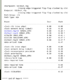
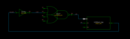
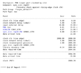
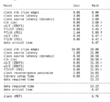
OK, I have an interesting question. Suppose you have a single flip-flop, where its input (D) comes from a combinational logic driven by its output (Q). In my opinion, the hold time violation in this case does not relate to clock skew or jitter at all, as we are inspecting the violation for that single flip-flop. But, something that I dont understand is that the Design Compiler uses the clock uncertanty (skew + jitter) in timing cacluation and becuase of that this structure violates in terms of hold timing. For example, see the following report generated by DC.