Continue to Site

Welcome to EDAboard.com

Welcome to our site! EDAboard.com is an international Electronics Discussion Forum focused on EDA software, circuits, schematics, books, theory, papers, asic, pld, 8051, DSP, Network, RF, Analog Design, PCB, Service Manuals... and a whole lot more! To participate you need to register. Registration is free. Click here to register now.

Hobby project: RC controller using tones and tone decoders

Status
Not open for further replies.

obrien136

Junior Member level 2
Joined
May 27, 2014
Messages
24
Helped
0
Reputation
0
Reaction score
0
Trophy points
1
Activity points
174
Hello,

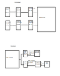
I was working on a 27KHz RC controller using tone generators in the transmitter and tone decoders in the receiver. It's kind of a PWM CW signal modulating a 27MHz carrier. The problem is I couldn't get the LM567 tone decoders to work. Attached is a block diagram of it. Does anybody else want to take a try at it?
rc control using tones.png
 
Last edited:

Tone coders and decoders were used in RC control from the very early days. Today PCM techniques are used that make the system more reliable and better resisting interference.
 
Tone coders and decoders were used in RC control from the very early days. Today PCM techniques are used that make the system more reliable and better resisting interference.

Was the overall approach the same as mine, with the pwm tone bursts and using the tones like subcarriers, or was there some other method?
 

I suppose there as many systems as manufacturers, but the system I came across is this:- A long sync pulse is sent, then a position where CH1 PWM pulse is sent, then another position where CH2 PWM pulse is sent. . . until end of channels then long sync pulse. I think the pulse train was sent in 10 mS, with the PWM entries limited to 1mS.
At the receiver the sync pulse resets all timers and counters. At end of sync pulse, gate opens for 1mS to allow CH1 sig out to CH1 output. Another gate opens from 1-2 mS to select CH2. . .
The PWM pulses are then compared with the PWM pulses coming straight of the servos and the motor on the servo turns the pot until the pulses have the same mark/space ratio, which means the servo has reached the correct position.
Is this standard?, have I remembered it correctly?
Frank
 

That sounds like the way I saw it in a book. I think that's right. Thta's how it's done now. I thought I had a new idea, but I guess it's already been done.

George
 

In regard to the 567 IC, it needs a stable incoming frequency. It is easily confused. It cannot pick its PLL frequency out of two simultaneous tones.

The output changes state when it detects a few cycles on its PLL frequency.
 

I didn't know that. In that case the whole idea was incorrect right from the start. I definitely won't pursue it any more. How did they employ the tone decoders in those days?

George
 

I didn't know that. In that case the whole idea was incorrect right from the start. I definitely won't pursue it any more. How did they employ the tone decoders in those days?

George

Unfortunately, "those" days includes when I was building and flying my first RC models -- never could afford a multi-channel reed receiver. Here is one link: http://www.rchalloffame.org/WhoFirst/First01/index.html

The reeds in the receiver were resonate to the subcarriers. Orbit (mostly) and Bonner were major players. For more history go to the American Academy of Aeronautics site (AMA, http://www.modelaircraft.org/ ).

I agree with your decision to drop that approach.

John
 

In regard to the 567 IC, it needs a stable incoming frequency. It is easily confused. It cannot pick its PLL frequency out of two simultaneous tones.

I think the statement needs clarification. As long as the tone decoders are operated in their linear range, they should be well able to "pick it's frequenyc out of two (and more) simultaneous tones". As an example, see the touch-tone decoder in the LM567 datasheet. One possible reason why the tone decoder may fail is overload.

Nevertheless there are better methods for multi-channel RC available these days.
 

I think the statement needs clarification. As long as the tone decoders are operated in their linear range, they should be well able to "pick it's frequenyc out of two (and more) simultaneous tones". As an example, see the touch-tone decoder in the LM567 datasheet. One possible reason why the tone decoder may fail is overload.

Yes, I forgot in the years since I experimented with the 567. It will pick its frequency out of two simultaneous sinewaves. This type of signal is generated in telephone dialing. The 567 is recommended for decoding these.

However if the waveform is too complex, or is not within a particular amplitude range, the IC will have trouble detecting its frequency.
 

However if the waveform is too complex, or is not within a particular amplitude range, the IC will have trouble detecting its frequency.
There's an essential limitation of the LM567, it's I- and Q-phase-detectors are also sensitive to odd harmonics of the VCO frequency. That's why a circuit using 5 and 15 kHz most likely won't work.
 

There's an essential limitation of the LM567, it's I- and Q-phase-detectors are also sensitive to odd harmonics of the VCO frequency. That's why a circuit using 5 and 15 kHz most likely won't work.
Yes , if I was to continue with this project I would change the frequencies, but I couldn't get it to respond to a single tone. I don't have a scope anymore. What range of amplitudes does it work? I didn't see it in the data sheet.
 

Status
Not open for further replies.

Part and Inventory Search

Welcome to EDABoard.com

Sponsor

Back
Top