Continue to Site

Welcome to EDAboard.com

Welcome to our site! EDAboard.com is an international Electronics Discussion Forum focused on EDA software, circuits, schematics, books, theory, papers, asic, pld, 8051, DSP, Network, RF, Analog Design, PCB, Service Manuals... and a whole lot more! To participate you need to register. Registration is free. Click here to register now.

High voltage supply 5kV DC

Status
Not open for further replies.
Hi all,

I had made a voltage multiplier using SMD capacitors and diodes. (0.1uF 1000V capacitors, 1 A, 1000V diodes). I made two PCBs, however, the circuit is behaving randomly and I hardly get any voltage above 3kV (Best case). I made the circuit in two rows as shown in Fig.. Individually the two layers are able to give the correct voltage multiplication factor. However, when i connect them, it still gives around 2.5kV when the voltage should be atleast 6 kV. Is this to with layout or circuit components(smd capacitors). Generally what i have seen in articles is that capacitor used is 22nF,1000V. But this is 0.1uF, still its not working. What could be the issue
 

Attachments

  • Layout.pdf
    20.4 KB · Views: 90

What is the driving source voltage and waveshape and impedance? I note the current limiting resistors on the pcb - what is the load? how are you measuring the 3kV ... ?
 

    sabu31

    Points: 2
    Helpful Answer Positive Rating
What is the driving source voltage and waveshape and impedance? I note the current limiting resistors on the pcb - what is the load? how are you measuring the 3kV ... ?
Its AC supply 230V 50Hz. I am using cokcroft walton multiplier (half wave type).
 

Well that is some of my questions answered, at 50Hz, you will need bigger caps ...
 

Well that is some of my questions answered, at 50Hz, you will need bigger caps ...
Thank Easy Peasy for the reply.

However, typically for Air Ionizers(based on voltage multiplier), 22nF/10nF capacitors are used (internet resources) .
 

peak mains is 325V for a good sine wave source - lets say 280Vpk, to get 6kV peak you need, 6000/280 = 22 stages, and this is with very minimal load on the o/p. Let us say you want 5 watts, this is 800uA, 22 100nF caps in series is 4.54nF at 6kV, with an 800uA load the rate of discharge is i/C = dv/dt = 176V per milli-second, so if the time between chargings is 8.5mS say, the droop will be 1500V, it seems unlikely the charging pulses will keep up, to limit the droop to 2% ( of 6kV ) the caps need to be 12.5 x bigger, i.e. 1.25uF, say 1.5uF 400V each.
Thi will get you a lot closer for a 5W load ... also the diodes need to be low leakage ...
 

    sabu31

    Points: 2
    Helpful Answer Positive Rating
peak mains is 325V for a good sine wave source - lets say 280Vpk, to get 6kV peak you need, 6000/280 = 22 stages, and this is with very minimal load on the o/p. Let us say you want 5 watts, this is 800uA, 22 100nF caps in series is 4.54nF at 6kV, with an 800uA load the rate of discharge is i/C = dv/dt = 176V per milli-second, so if the time between chargings is 8.5mS say, the droop will be 1500V, it seems unlikely the charging pulses will keep up, to limit the droop to 2% ( of 6kV ) the caps need to be 12.5 x bigger, i.e. 1.25uF, say 1.5uF 400V each.
Thi will get you a lot closer for a 5W load ... also the diodes need to be low leakage ...

I am infact doing open circuit measurement. For safety purpose i have kept 20Meg Resistors. Is there any issue with layout or capacitor type used.
 

How can anyone answer your question when you haven't presented the part number for the capacitors??? - what type is it...? for that matter what diode are you using? Irrespective of all that - your caps are too small ...
 

how are you measuring the Vout ...?

Thanks Easy Peasy for the reply.
I am measuring Vout using Multimeter Fluke 289 ( i have kept 390Meg resistors in series and there is 10 Meg internal resistor ). I am doubting if there is a loading issue. Earlier circuits worked (at that time capacitors were 47uF). Now since the capacitors are 0.1uF, the multimeter measurement could be loading the system. what could be the issue.
 

What is a total load resistance ? including the metering ... ?
Its 420 Meg Ohm.

Will smoke test in a 2litre bottle work for capacitors sized at 0.1uF. It had worked when i used full bridge multiplier (but the capacitors were 47uF).
 

420 M-ohm is 14.3uA @ 6kV ( 86 m-watt ) 22 stages to get to 6kV, total C = 4.5nF i/C = dv/dt, thus in the 8mS off time the Vout will fall 26V - so you should get to 6kV if the diodes are not leaky ...
 

420 M-ohm is 14.3uA @ 6kV ( 86 m-watt ) 22 stages to get to 6kV, total C = 4.5nF i/C = dv/dt, thus in the 8mS off time the Vout will fall 26V - so you should get to 6kV if the diodes are not leaky ...
Thanks Easy Peasy for the Reply.

The following are the components I have used


Circuit 1 ( (30 Stages)) All using SMD components
Capacitor
C1812C104KDRACAUTO - SMD MLCC, 0.1 µF, 1 kV, 1812 [4532 Metric], ± 10%, X7R, C Series KEMET
Diode
S1M-13-F - Standard Recovery Diode, 1 kV, 1 A, Single, Vf= 1.1 V, 1.8 µs, 30 A


Another Circuit I made using 24 stages.
1n4007 and 68nF,630V (Polyester Film Capacitor)
Both circuit is not going above 2.5 kV voltage when measured through multimeter/ HV probe (500Mohm)


How do I know if ionizer circuit is working. Can layout (keeping the components closer/ using SMD component Vs Through Hole) affect the functioning of the system. What should be done to see visible smoke clearance (in a smoke chamber test using 2 litre bottle)
 

better diodes needed ... the leakage is 100uA at 125 C, so could be anywhere up to this figure for an odd batch

given that your load is 14.3uA it is not surprising you are losing volts - special low leakage diodes are usually used for volt multiplier ladders ...

bigger capacitors will help overcome this issue at the expense of leakage current heating in the diodes ...
 
Last edited:

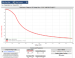
Another point to consider, these X7R HV capacitors have only about 25 % of rated capacitance at 500V DC. Check Kemet K-SIM tool.

1593587737318.png
--- Updated ---

I agree that diode leakage can be a big problem. But I guess that the actual leakage current of S1M-13-F at 25°C is far below 1 µA.
 
Last edited:
  • Like
Reactions: sabu31

    sabu31

    Points: 2
    Helpful Answer Positive Rating
maybe of a high quality one - an ali-express one could be anything - have you measured one lately ....? at 300 volts piv ...?

the data sheet says 5uA typ @ 25 deg C and up to 100uA at 100 deg C - so batch variations could yeild 100uA per device easily ...
 

Status
Not open for further replies.

Similar threads

Part and Inventory Search

Welcome to EDABoard.com

Sponsor

Back
Top