Continue to Site

Welcome to EDAboard.com

Welcome to our site! EDAboard.com is an international Electronics Discussion Forum focused on EDA software, circuits, schematics, books, theory, papers, asic, pld, 8051, DSP, Network, RF, Analog Design, PCB, Service Manuals... and a whole lot more! To participate you need to register. Registration is free. Click here to register now.

High voltage supply 5kV DC

Status
Not open for further replies.

sabu31

Advanced Member level 1
Joined
Jan 28, 2011
Messages
441
Helped
12
Reputation
24
Reaction score
13
Trophy points
1,298
Activity points
5,103
Dear All,

I need to develop at circuit with 5kV and 10-20mA supply DC. I need to develop it for demo purpose. So I am not looking into closed loop control and if possible transformer-less and without use of active semiconductors(mosfet,igbt). What topology could be a starting point. Is there any voltage multiplier circuit for converting utility ac to 5kV. Please suggest any topologies/reference designs/materials.

Thanks
 

The simplest is a simple voltage multiplier but it has no isolation between the incoming AC supply and the output so depending on the circumstances, it could pose an electrocution risk.

If we assume a standard C-D multiplier is 100% efficient (it isn't!) you need to multiply 115V AC mains with a peak of ~160V by 31 times or a 220V supply with a peak of ~312V by 16. Each multiplier stage loses you about 1V in diode drop so you probably need at least one extra stage.

It can be made safe if you can use an isolating transformer at the AC input and ground one side of its secondary.

Brian.
 
  • Like
Reactions: sabu31

    sabu31

    Points: 2
    Helpful Answer Positive Rating
Thankyou stenzer for the reply. I am using standard 220 V supply as input.

- - - Updated - - -

Thankyou betwixt for the reply. Can you give link to the multiplier circuit. Also is it possible to reduce the number of stages. For isolation, can we use ferrite core E65 as its difficult to procure isolation transformer here due to covid issues.
 

Hi,

the villard circuit is a simple voltage doubler/multipier and as betwixt mentioned, without a mains transformer it might be hazardous to operate the circuit.

As betwixt mentioned at each stage a voltage drop across the used diodes occure. Assuming a total drop of 1.4 V and a 220 V • √2 ≈ 310 V amplitude, than at least 5 stages are required to gain a voltage above 5 kV. 5 stages are resulting in an output voltage of 9882.6 V, four stages in 4941.80 V. If your mains voltage is 230 V, four stages already resulting an output voltage larger than 5 kV (5186 V).

Greets
 
Last edited:

can we use ferrite core E65
No, I was thinking of a mains isolating transformer to eliminate the risk of direct connection to the AC power lines. Without one you can generate the high voltage but one side of the output will be directly linked to the AC power source and therefore a hazard of electric shock exists. The type you want is a small 220V:220V isolator which will almost certainly have an iron core.

Brian.
 
  • Like
Reactions: sabu31

    sabu31

    Points: 2
    Helpful Answer Positive Rating
Thanks for the reply betwixt. procuring iron core is one is one issue during these times. I have some stock of ferrite cores. But rough calculation is requiring a huge number of turns of the order of thousand. What the risk factor of electric shock and what safety protections are to be used when using non isolated configuration.
 

Do you "need" the volts and milliamps, or do you "need"
to perform the development?

There's little HV supplies being sold on eBay fully potted,
~5V DC in, various voltages out (I bought a couple of
400kV ones for bug zapper projects).
 
What the risk factor of electric shock and what safety protections are to be used when using non isolated configuration.
A diode/capacitor voltage multiplier needs two inputs, these would probably be the wires to the AC wall outlet. One of the output wires will be directly connected to one of the input wires so the danger is the same as touching the AC wiring. Potentially, it will have full AC mains on it and therefore a risk of electrocution. There isn't much you can do to make it safe unless the whole thing is completely enclosed and has no outside connections.

A ferrite core is of little use as a mains isolating transformer, they are better suited to higher frequencies than 50/60Hz. At low frequency they are very inefficient and as you say would need thousands of turns on both the primary and secondary windings.

Brian.
 

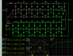
Example of Cockcroft-Walton voltage multiplier. Powered by mains 230 VAC. Since the peak is 330V, each stage might add 330V except that multiple diodes take a toll.
10 stages. Scope traces monitor every third capacitor. Notice successive stages charge to a lesser volt level.

V multiplier Cockcroft-Walton 10 stage 230VAC supply  output 3 kVDC 10mA.png

With no load, output can rise to 3.27kV DC.
10mA load pulls it down several percent.

To obtain negative polarity, reverse all diode directions.

The 2 ohm resistor is not absolutely necessary. It's there to limit initial current surge, and to clarify waveforms.
 
  • Like
Reactions: sabu31

    sabu31

    Points: 2
    Helpful Answer Positive Rating
I believe what we need to know is precisely what Dick_Freebird just asked:

-Does the OP "needs to design" such a supply?
-Or does he/she requires an actual functional unit for another experiment? Like a Jacob ladder?

The best solution depends on the answer.
 

Easiest is a TLC555 set to 35% pwm output, buffered with emitter follower ( 12V supply ) driving a 600V mosfet or IGBT, 7-8 kHz - so you can hear it for safety

flyback Tx on an ETD 49 or similar, or larger, DCM ( discontinuous mode ) with 5 output wdgs, and 3 x 800V diodes on each ( can use 1N4007's at 5kHz )

each wdg with its own set of diodes and 10nF 1500V cap to catch the energy, these o/p's stacked in series to give the 5kV @ 10mA

the flyback volts on the 600V device is to be 500V max, so the turns ratio is 1 : 2

So, possibly 10 turn pri and 20T sec's - need to be worked out for peak Bin core for the ON time ... and core size ( dB/dT = V/N.Ae )

plenty of sellotape to insulate the wdgs will serve for a year or two ...

- - - Updated - - -

[ for e.g. 5kHz, ETD49/220mm^2, Ton = 70uS ( 35% ) dB = 0-0.3T gives N pri = 14T for 12V power source ]

=> Nsec = 28T for a flyback of 500V on the pri side, Vrev-pk on the sec side diodes = 24V + 1kV = 1200 volt say ...

- - - Updated - - -

hi hi - forgot to do the gap, power = 5kV, 10 or 20mA = 50 or 100W

for 50W, 100 = freq . L . I^2 in prim and V/L = di/dt so for Vsupply = 12V and t = 70uS, 12/L = di / ( 70uS ), or L = 0.00084 / di

=> 100/5kHz = 84E-3 . di or di = 23.8Apk, and L = 35.3 uH, Energy in gap = 0.5 B . H . Vol gap = 0.5 L I^2 = 0.01 ( joule ) [ B=Uo.H ]

hence Vol gap = ( Ae . lg ) = 279E-9 m^3 & lg = 1.27mm, <= this is the gap in the centre pole or 0.7mm in each leg...!

Now AL = so many nH/N^2, = Uo . Ae/lg = 217.7 nH/N^2 => Npri = 12.73 turns, say 14 turns Nsec = 28 Tuns

note 23.8Apk but the ave input current will be around 5 amps at full Vout and 50W load, 70uS on time + 70uS off time = 7.1 kHz which is audible

at the start of power up, and when at full Vout the off time need only be V/L = di/dt, 500/35.3uH = 23.8A / dt, => dt will be 1.68uS, and the freq can be 14kHz ...
 
Last edited:
  • Like
Reactions: sabu31

    sabu31

    Points: 2
    Helpful Answer Positive Rating
For isolation, can we use ferrite core E65 as its difficult to procure isolation transformer here due to covid issues...

5 kV at 10-20mA works out about 100W. You need to worry about losses (voltage multipliers are not lossy but with 10-20 times multiplication you will get very poor regulation).

You can use a ferrite core but use a higher operating frequency (say 5-10 kHz). Design for an output voltage of 1000v and 100mA current. Check whether your core can handle the power. But you do not want to use semiconductors?

You will need good (fast) diodes and low loss capacitors. Something like these?:)

But you cannot use the E65 core transformer at 50Hz as the isolation transformer.voltage-multiplier.jpg

To get 10-20mA current you may need huge capacitors.

- - - Updated - - -

There is a nice video:

https://www.youtube.com/watch?v=ep3D_LC2UzU

Perhaps some useful pointers?
 

Example of Cockcroft-Walton voltage multiplier. Powered by mains 230 VAC. Since the peak is 330V, each stage might add 330V except that multiple diodes take a toll.
10 stages. Scope traces monitor every third capacitor. Notice successive stages charge to a lesser volt level.

View attachment 158889

With no load, output can rise to 3.27kV DC.
10mA load pulls it down several percent.

To obtain negative polarity, reverse all diode directions.

The 2 ohm resistor is not absolutely necessary. It's there to limit initial current surge, and to clarify waveforms.

Is it possible to use Electrolytic capacitors and how do we design capacitor. I saw in simulation that the capacitor voltages are not swinging from +ve to -ve so thought of using electrolytic capacitors
 

Hi BradtheRad,

In layouting, I want to fit the circuit in a single board. Can it done as follows

<blockquote class="imgur-embed-pub" lang="en" data-id="a/Lur4KlI" data-context="false" ><a href="//imgur.com/a/Lur4KlI"></a></blockquote><script async src="//s.imgur.com/min/embed.js" charset="utf-8"></script>
Does it make any difference in relation voltage breakdwon
 

Is it possible to use Electrolytic capacitors and how do we design capacitor. I saw in simulation that the capacitor voltages are not swinging from +ve to -ve so thought of using electrolytic capacitors

Yes, electrolytic type can be used. Cockcroft-Walton type is popular because no individual component is exposed to voltage greater than peak of AC supply. This means you can use 400V rating for all diodes and capacitors.

All caps should be the same Farad value. Higher values can deliver higher mA.
Notice C1-C10 all discharge 10mA to the load. Therefore each must be charged by a brief pulse coming through the network.

--------------------------

Your board layout is suitable. Find out the size of 100uF 400V electrolytic. It's huge (as post #14 points out).

Our tendency is to use a lesser value in hopes it can work okay. However this still requires up to 100 Watts going into your project (5000 x .02). Lesser Farad values require that you build additional stages if you want to achieve 5kV 20mA.
 
  • Like
Reactions: sabu31

    sabu31

    Points: 2
    Helpful Answer Positive Rating
It should be pointed out that once you get to >1kV with > 100uF storage, with mains supplied energy - the device becomes lethal for mistakes by any operator ...
 
  • Like
Reactions: sabu31

    sabu31

    Points: 2
    Helpful Answer Positive Rating
I woke up on the floor of the shed one time after
playing with a car ignition coil and NiCd batteries.
Given the state of the shed, waking up was a matter
of luck....
 

    tony_lth

    Points: 2
    Helpful Answer Positive Rating
I have obtained an isolation transformer 500VA size and intend to use along with auto transformer for gradual increase in voltage. I have decide upon full bridge cockroft walton. using 47uF,400V cap (which is only cap that I have). I intend to use for air ionizing applications and along with other applications also so I hope the loading wont be an issue. Using isolation transformer should make system safe right? or is there any other precautions to be taken. Thanks
 

Status
Not open for further replies.

Similar threads

Part and Inventory Search

Welcome to EDABoard.com

Sponsor

Back
Top