Continue to Site

Welcome to EDAboard.com

Welcome to our site! EDAboard.com is an international Electronics Discussion Forum focused on EDA software, circuits, schematics, books, theory, papers, asic, pld, 8051, DSP, Network, RF, Analog Design, PCB, Service Manuals... and a whole lot more! To participate you need to register. Registration is free. Click here to register now.

High Voltage Signal generator

Status
Not open for further replies.

Max++

Junior Member level 3
Joined
May 24, 2006
Messages
29
Helped
0
Reputation
0
Reaction score
0
Trophy points
1,281
Location
Thailand
Activity points
1,495
I'm building a signal generator which simulate unstable of power line such as Dip, Swell, Transient, Harmonic etc.

The concept that I done is that generate signal from ADC and then input to amplifier and finally transformer.

I encounter the problem while generated the signal of transient.
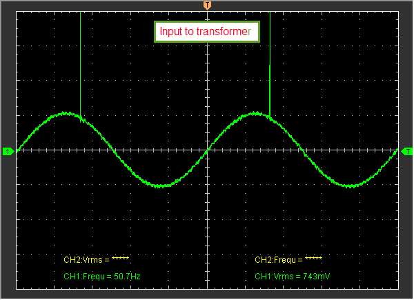
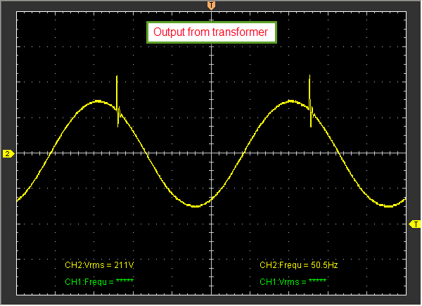
I found that the transformer can't response the transient voltage and give very low voltage to output even if force maximum level to input (as attach images).


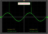
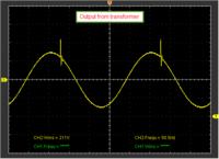
I think the transformer can't response to high frequency cause of the transient time is only 1uSec(1MHz).

Could you please give me some idea to solve this problem?
 

Hi,

Maybe the corematerial is not able to handle the high frequency of the pulse.
Either use a transformer with ferrite core,
Or maybe it is possible to use two transformers in serial, one standard transformer for the power sine, the other withe ferrite handling only the pulse.
Mind to generate absolutely DC free signals to the inputs of the transformers.

How much watts or amperes can handle your generator at the output?
Interesting application.

Klaus
 

The concept that I done is that generate signal from ADC and then input to amplifier and finally transformer.
I guess you mean DAC signal generation?

Signal generators with power amplifiers are commonly used for line voltage related EMC tests and e.g. mentioned in various IEC 61000-4-xx test setups. I would mainly expect high voltage amplifiers without transformers in similar instruments. But if transformers are used they must be designed for the respective signal bandwidth and circuit impedance. It's not quite clear which range of EMC tests you address with your design. Some test specifications are demanding high peak currents and can't be easily met with an amplifier based generator. In so far, the idea to perform many different tests with one universal test generator might be unrealistic.

In the present case, a transfomer designed with considerably lower leakage inductance would reproduce the primary waveform at the secondary much better. But will the amplifier deliver the same pulse waveform with a much higher current?

Fast pulses can be also superimposed to the line voltage by coupling networks, as in standard surge and burst tests.
 

Hi, KlausST
Thank you for your answer. This project is voltage based, so it give very low output current at output (<10mA).

- - - Updated - - -

HI, FvM

Sorry for my mistake it should be DAC instead of ADC.

As your idea, may I know the concept of amplifier which able to give high voltage at output as you mention.
Please provide the IC number or circuit. I would be appreciated.
 

I have no specific circuit in mind, just a discrete HV power amplifier. You can review the internet publications about "kW MOSFET amplifiers" for audio applications to get an idea.
 

Hi,

I´d try a ferrite core transformer.

You know a 10 mA @ 230V gives about 250mA @ 12V (with loss).

This is about a 50 ohms load. Maybe you can try wide bandwidth power opamps.
If possible use AC coupling of transformer primary side.

Hope this helps

Klaus
 

I would go for a two transformer solution with a combiner, rather like a loudspeaker cross over unit. Use an LF transformer for your 50 HZ power and feed it to the output via a ferrite choke capable of carrying the 50 HZ current without saturating. Feed you HF transients into a ferrite based pulse transformer and connect this to the output via a suitable capacitor (.001 MF?) which can withstand the 230V AC. By testing the frequency response of the LF transformer, you can see where it rolls off, So now you can apply a pre-corrected response to the HF transformer to get the over all response you require.
Frank
 

Status
Not open for further replies.

Similar threads

Part and Inventory Search

Welcome to EDABoard.com

Sponsor

Back
Top