Continue to Site

Welcome to EDAboard.com

Welcome to our site! EDAboard.com is an international Electronics Discussion Forum focused on EDA software, circuits, schematics, books, theory, papers, asic, pld, 8051, DSP, Network, RF, Analog Design, PCB, Service Manuals... and a whole lot more! To participate you need to register. Registration is free. Click here to register now.

High Voltage Buck Converter

Status
Not open for further replies.
Hello everyone,

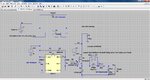
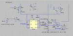
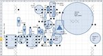
I've changed my IRF640NPbF nMOS into IRFB4227PbF and adding a 200V 100uF bypass cap decoupling the +HV 100V (see attached schematic).

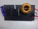
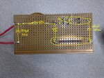
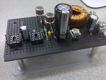
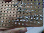
Upon turning on my HV 100V PSU, the stripboard suddenly smokes and an awful smell is given off. Went to check what's wrong and realised there is an interesting distinct path that was burnt (see buck_on_stripboard_back.jpg). The components facing side photo is also uploaded (see buck_on_stripboard_face.jpg).

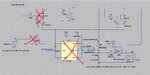
From my guess, when I've turned on the 100V PSU, a surge travels down starting from the MOSFET's drain, 100uF supply bypass cap, schottky (FW) diode and to somewhere else.

The schottky diode was found to be damaged. The burnt marked also ends at the anode of the schottky. But what I did not understand is why didn't the current continue to flow pass the anode of the FW diode and all way to GND, but instead through the diode.
 

Attachments

  • buck_on_stripboard_face.jpg
    buck_on_stripboard_face.jpg
    143.4 KB · Views: 94
  • buck_on_stripboard_back.jpg
    buck_on_stripboard_back.jpg
    266.3 KB · Views: 92
  • IR2117withTC4420(1).jpg
    IR2117withTC4420(1).jpg
    431.8 KB · Views: 79

HI guys,

Im back. I've put everything on a board.

When I turned on the 100V PSU, by slowly ramping up the DC voltage starting from 0V, only 2 out of 10 times will produce the expected result. The other 8 times, either they have no response, as in no o/p voltage or the drain and source got short together, destroying the MOSFET.

Does anyone knows why? I've appended my circuit, PCB layout diagram, as well as the actual photo. Basically, everything.

Any comments are welcomed.
 

Attachments

  • full_sch.jpg
    full_sch.jpg
    176.9 KB · Views: 78
  • sch_grid.jpg
    sch_grid.jpg
    215 KB · Views: 72
  • full_front.jpg
    full_front.jpg
    121.1 KB · Views: 72
  • full_back.jpg
    full_back.jpg
    141 KB · Views: 71

Hello My friend
At first step , How much is your feedback voltage at max.
at 2nd step , Why you used SW2?
Best Wishes
Goldsmith
 

Hello My friend
At first step , How much is your feedback voltage at max.
at 2nd step , Why you used SW2?
Best Wishes
Goldsmith

Hi Goldsmith,

How are you? There is no feedback in my circuit yet, but the o/p voltage is about 28V DC.

The SW2 is there just to simulate a more realistic inductor in my simulations. It closes the switch as long as the DC current reaches a certain value, which in turn, decreases its effective inductance.

Are you good and familiar with SMPS?
 

Dear Friend
I'm fine , thanks , how are you too? . As you can see at my profile , SMPS systems are my friends from 5 years ago until now.
As i can see at your attachment , you used a zener diode in parallel with your gate source , with 5.6 volt?! if your GS voltage is not about +15 volt , thus your mosfet is at linear region , and it means high value of dissipation .
BTW , why you didn't use a discharge resistor , in parallel , with your GS?
Things that i said are most important things that destroyed your circuit simply. and what is the value of your series resistor with the gate?
Best Wishes
Goldsmith

I am great, thank you. Yup, the 5.6 is the ohms for Rgate, not the zener diode in parallel with GS. Instead, the GS's zener is 12V, which is what I've set for all the Vdd for control's ICs.

I do not know of your method in adding a resistor in parallel with GS? what does it do? Does it absorb the transient when GS is switching? If it is, my zener diode is actually there for that. If you're suggesting additional protection, shouldn't we add RC instead of just R alone?

I did try this circuit on my breadboard and it works very well. The only downside is the huge transient occuring at the GS but this is expected because oh my long wires connecting here and there. When I've transferred all those wirings onto stripboard, the transients are gone! But a new problem arises which is everytime I slowly ramped 0-100V of the power supply unit, it sometimes could start, sometimes dont.

That is not what I want.
 

The GS resistor aim : the GS has capacitor , ( parasitic) , if that capacitor , become charge , it can not be discharge because
The Input impedance is about infinite . that resistor is for more safety .
And your circuit should have feed back to be stabilized .
Respect
Goldsmith
 

The GS resistor aim : the GS has capacitor , ( parasitic) , if that capacitor , become charge , it can not be discharge because
The Input impedance is about infinite . that resistor is for more safety .
And your circuit should have feed back to be stabilized .
Respect
Goldsmith

Right, but before I implement feedback, I want to try open loop first. My open loop on breadboard gives me an o/p accurate up to +/- 1V. If the open loop buck on stripboard doesnt always work, lets not talk about closed loop. I really need to solve the "sometime can, sometime not" problem as for now.
 

I can't believe that you want do it on brad board!!!!!!!!!!!!!!!!!!!! it is possible that your connections ( Fast diode) is not well , thus your mosfet can not tolerate the high voltage spikes.
 

I can't believe that you want do it on brad board!!!!!!!!!!!!!!!!!!!! it is possible that your connections ( Fast diode) is not well , thus your mosfet can not tolerate the high voltage spikes.

I think you've misunderstood me. What I meant was I had already tried on breadboard w/o much problem except for getting large transient. This transient could be from the long wires that I've wired around which is unavoidable when on breadboard.

Ironically, when I transferred all these components from breadboard to stripboard, sometimes I could start, sometime I cannot. That is my issue NOW! Haha.
 

Again Hi
About 6 month ago , i made , a push pull Smps , on strip boar , and it's power , was about 2KW . it was not problem . did you used star ground ? at high frequency , designs , the star ground is very important.
Good luck
Goldsmith
 

Again Hi
About 6 month ago , i made , a push pull Smps , on strip boar , and it's power , was about 2KW . it was not problem . did you used star ground ? at high frequency , designs , the star ground is very important.
Good luck
Goldsmith

Hello... If I am not wrong, isnt star ground for 3 phase systems? My systems is a 100V DC, stepped down to 28V DC, everything is a DC to DC operation.

By the way, upon checking continuity check for every side by side copper strips, I've found out that some has intermittent shorts! Which means there are times when the DMM showed it shorted, sometimes it doesnt. That is scary!

SO what I did was to use a penknife to scratch one hard stroke on the breaks to prevent that. Do we have a better suggestion for this?

Cheers.
 

Star ground refers to a technique in circuit layout where different parts of the circuit are tied to one common ground point through separate ground traces, reducing crosstalk and EMI.
 

Star ground refers to a technique in circuit layout where different parts of the circuit are tied to one common ground point through separate ground traces, reducing crosstalk and EMI.

I see, I think mine is otherwise as you can see from my stripboard layout, that the ground is just a single trace. While it may introduce crosstalk, EMI and etc, does it possibly make my buck not working too. If yes, why?
 

Hello my friends
You have an analogue ground , and a digital ground , you should not connect them together , you should connect them together just at one point . if you don't this , your system will have many problem.
Respect
Goldsmith
 

Hello my friends
You have an analogue ground , and a digital ground , you should not connect them together , you should connect them together just at one point . if you don't this , your system will have many problem.
Respect
Goldsmith

I see. Btw which part of my circuit is analog, which is digital? Is the HV side analog and the ctrl part digital? Cheers.
 

Hi guys! im back.


Recently I've used a 8051 MCT to control the duty cycle (%) of the PWM I fed into the system to control the gate of the nMOS. The adjustment of the PWM (increase or decrease) is actually based on the output.


Mine operating logic is simple. If output is > 28.1V, decease PWM %, and if < 27.9V, increase PWM%, otherwise PWM duty cycle = no change.


My step change is about 0.4% because I am using an 8-bit register (256 steps in total).


However here comes the problem, quite oftenly, whenever the change occurs, the circuit will suddenly goes haywire. Components highlighted in the attached circuit marked with a red cross just suddenly "blow" out, killing them instantly.


Would anyone please advise, which component should I start looking into changing them for a better rating? I've really no idea and hope anyone with great electronic experience could give me some direction or pointers to let me start instead of wasting time on others..


Thanks in advance!
 

Attachments

  • full_sch_prob.jpg
    full_sch_prob.jpg
    181.2 KB · Views: 65

Hello Dear gdylp2004
At first step , i should say , welcome back ! : ;-)
Sorry because of that i forgot to reply your latest question before this question . the digital parts are , the parts that will work with logic sections and have square wave !

And what is your clear problem now ?
Best Wishes
Goldsmith
 

Status
Not open for further replies.

Similar threads

Part and Inventory Search

Welcome to EDABoard.com

Sponsor

Back
Top