Continue to Site

Welcome to EDAboard.com

Welcome to our site! EDAboard.com is an international Electronics Discussion Forum focused on EDA software, circuits, schematics, books, theory, papers, asic, pld, 8051, DSP, Network, RF, Analog Design, PCB, Service Manuals... and a whole lot more! To participate you need to register. Registration is free. Click here to register now.

High side IGBT damaging

Status
Not open for further replies.
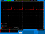
V cool, the caps on the bus also helped reduce the turn off spike (to nearly zero) after the turn off, leading to the cooler operating temps...!!!!!
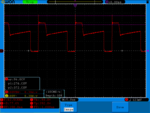
 
I can't really see how that transformer gate drive actually works...?! any one out there enlighten me...?
 

V cool, the caps on the bus also helped reduce the turn off spike (to nearly zero) after the turn off, leading to the cooler operating temps...!!!!!

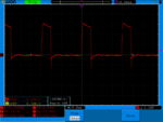
HELLO ORSON now i tried with 24volt and 35 amp load test.. this is the drain to source waveform is that ok? can i try another load ? the efficiency now appears to be near to 80%
oggiii.png
oggi 111.png
 

Yes, its all looking very good, the reset time for this level of power is about 4.5uS looking at the scope screens, it is proportional to on time and input voltage, looks like you can get more power if you wish, you may need more electrolytics on the main DC bus as there is quite a rise in HVDC after turn off (from 160V to 210V on the screen) - you may not mind this - so it isn't necessarily some thing that needs addressing, the turn off spike on the igbt could be addressed with 680pF (1kv ceramic cap) and 220 ohm (2-3W) as a guess for starters, across each igbt (RC in series) , this may reduce the spike a bit without incurring too much in the way of extra losses - also good for RFI / EMC...
Look forward to hearing how it all goes...!

hello, tomorrow i will try adding more caps tomorrow..
one another thing that i already have RCD snubber acroos the igbts C=4.7nf R=10ohms (3 watt/ 4watt). are thease values are ok?
 

Always good to experiment with snubbers, the D-C part gives you the ring and overshoot at turn off, try 10 ohms in series with the diode (or bigger) this may help, or just use an RC snubber (no diode) say 2.2nF and 220 ohm (3W) for starters - you need to vary the values to see what works in your circuit...
 
Always good to experiment with snubbers, the D-C part gives you the ring and overshoot at turn off, try 10 ohms in series with the diode (or bigger) this may help, or just use an RC snubber (no diode) say 2.2nF and 220 ohm (3W) for starters - you need to vary the values to see what works in your circuit...

ok i will try tomorrow and let you know how it works....

one another thing that i'm using a transformer from welding machine that was runnong on 80khz and mine circuit is running on 50khz so the point is if i increase the frequency it will improve somehing or not?
thanks
 

The transformer will have originally been designed around a maximum input voltage at the 80 Khz switching frequency.

You can run it at 50 Khz, but the maximum input voltage you can safely apply, needs to be limited to 5/8 of what was the originally specified maximum.

That may or may not be an issue for you.

so the easy thing to do is increase the frequency to 80khz and it will work fine....
 

That is obviously going to work.
But it will potentially increase switching losses.
If you require full rated output voltage and output power, its the only way.
 

You can tell what switching frequency is best by the temp of the transformer, 50kHz seems to be going OK, so maybe 60kHz max, as you have a reduced input voltage, i.e. lower than the welder, looking at your scope shots, as you go higher in freq the igbt losses go up as do the snubber losses and the Tx wire losses, the core losses may stay the same.
Its all about temp rise - it may be good for you to raise the freq and see what gets hot - this is the best way to learn and teaches you a lot - good luck..!
 
Temperature rise is a very good indication of losses.

Another way is to measure dc input and output power, and calculate efficiency. That is a much faster way as you don't have to wait for everything to temperature stabilize.
Try it at 50, 60, 70 Khz and see how it goes.

That should give you a pretty good feel for what is going on, and where the main losses are.
As Orson says, its all jolly good fun, and very instructive.

You can tell what switching frequency is best by the temp of the transformer, 50kHz seems to be going OK, so maybe 60kHz max, as you have a reduced input voltage, i.e. lower than the welder, looking at your scope shots, as you go higher in freq the igbt losses go up as do the snubber losses and the Tx wire losses, the core losses may stay the same.
Its all about temp rise - it may be good for you to raise the freq and see what gets hot - this is the best way to learn and teaches you a lot - good luck..!

hello everybody as you said i did the test changing thefrequency the temprature rises about 5C of heatsink and the efficiency come down from 78% to 75%...
 

Most of your losses must be conduction losses rather than switching losses, so that is where it might need a little more work.
Still its not too bad considering the high output current which is always problematic.

What is getting hot should be a pretty good guide to where the watts are escaping.
 
Most of your losses must be conduction losses rather than switching losses, so that is where it might need a little more work.
Still its not too bad considering the high output current which is always problematic.

What is getting hot should be a pretty good guide to where the watts are escaping.

how can i improve conduction losses? :)

i think the igbts are getting hot the reset diodes and igbts are mounted on the same heatsink because the transformer is not heating up...
thanks again
 

The measured forward voltage drops will be a strong clue.
Compare what you are seeing to the device specifications, and see if it is reasonable.

Compare some different available devices, high voltage mosfets as well as IGBTs, and how they might perform in your circuit.
When paralleling multiple devices, the combined conduction losses of mosfets and IGBTs behave very differently.

You are running two devices in parallel. Perhaps three or four in parallel might significantly reduce conduction losses, or it may make little overall improvement.
But you can work it all out from published data, conduction voltage drop versus current for each device.

I am working on a 1.5Kw boost converter right now.
One IGBT beats one high voltage mosfet easily.
Two IGBTs in parallel are about the same as two mosfets in parallel.
Adding more, perhaps four mosfets in parallel works out being miles ahead in conduction losses compared to four IGBTs in parallel.

It does not always work out quite like that, depending on relative voltage and current involved, and the particular devices, but there may be significant gains to be had by exploring a few hypothetical alternatives.

sorry i haven't told that i'm running on only to igbts .. to not to burn because they are a bit expensive here in italy... :p
i will try to parallel igbts and then see what happens...
 

HELLO GUYS :)
Now i'm on output stage.. i looked with oscilloscope my circuit output and that was very ugly

i have 4700MF capacitor and 50uH high Amp rated inductor and that is what i'm getting :???:
HJJ.png

i know i'm asking soo much questions.. sorry about that but i want to learn and improve my design...

- - - Updated - - -

that is on 24V 30A resistive load and like you already know the transformer is 155 Amp rated...
 

That looks pretty normal, do you have snubbers on your o/p diodes? I take is the scope shot is from a current sensor?

- - - Updated - - -

If that is your o/p voltage scope shot the extra bits on top are due to the ESR & ESL in your big o/p electro, more film caps needed to smooth this out 10uF say, or 5 x good quality electro's in parallel

yes this is my output stage voltage, so have to change capacitors and add some film caps to smooth the output?

i have the snubbers on output diodes and the voltage spike on output diodes with snubbers is 30 volt
 

Status
Not open for further replies.

Part and Inventory Search

Welcome to EDABoard.com

Sponsor

Back
Top