Continue to Site

Welcome to EDAboard.com

Welcome to our site! EDAboard.com is an international Electronics Discussion Forum focused on EDA software, circuits, schematics, books, theory, papers, asic, pld, 8051, DSP, Network, RF, Analog Design, PCB, Service Manuals... and a whole lot more! To participate you need to register. Registration is free. Click here to register now.

high power charge pump

Status
Not open for further replies.

Peng Yao

Newbie level 4
Joined
Apr 20, 2014
Messages
7
Helped
0
Reputation
0
Reaction score
0
Trophy points
1
Activity points
47
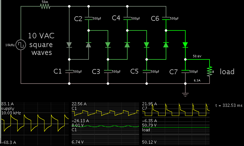
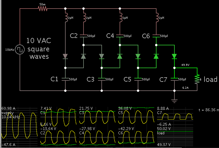
Is it possible that a charge pump could provide maybe 300W in the output? for example 50V and 6A in output? Thanks!
 

source voltage is ...say 5V or 10V?
 

Multiple charge-pumps can be cascaded, to produce several amperes.

The supply is 10 VAC square waves. The load gets 50 V at 6.3 A.

Notice the supply must provide several tens of amperes.


If the supply were 10V pulsed DC, more stages of charge-pumps would be needed.
 
I suggest a sligthly modified posing of the question: "Is it reasonable to design a 300 W DC/DC converter as charge pump"?

I suppose, the answer is No.
 

Hello Brad, I like your circuit, the addition of some small inductors in series with C2,4,6 and the far left upper diode will make it efficient at 10kHz and higher frequencies...
 
thanks...the reason why I ask this question is that I found that the charge pump usually used in that application which only required low current...and I want to know if there is any fundamental limitation about it...now I know it is possible to get high current...what kind of charge pump what u build...cuz I only now dickson charge pump and it required a non-overlapping clock generator...I want to simulate ur charge pump...can u provide me more detail about ur circuit? many thanks!!!

- - - Updated - - -

I know it is not reasonable...
 

Hello Brad, I like your circuit, the addition of some small inductors in series with C2,4,6 and the far left upper diode will make it efficient at 10kHz and higher frequencies...

Yes. Adding those inductors does improve performance.
It eliminates the spikes which surge through the diodes and capacitors.


The scope traces reveal that no spikes occur in any capacitor.

The Henry values were custom adjusted, to produce a slight softening effect on the waveforms.

- - - Updated - - -

thanks...the reason why I ask this question is that I found that the charge pump usually used in that application which only required low current...and I want to know if there is any fundamental limitation about it...now I know it is possible to get high current...

Each capacitor must carry as much as 16 Amperes, back and forth during each cycle. This causes stress on them.

ESR becomes important. If a cap has just 1/50 of an ohm internal resistance, it generates 5 W of heat. (16A x 16A x .02).

Large capacitors are needed to handle several amps of current. The cost of several large capacitors can add up.

Also notice each diode wastes several watts as heat.

These could be reasons why charge-pump topologies are not typically used in high-current applications.

what kind of charge pump what u build...cuz I only now dickson charge pump and it required a non-overlapping clock generator...I want to simulate ur charge pump...can u provide me more detail about ur circuit? many thanks!!!

There are several charge-pump topologies. This link shows several, with comparisons pro and con.

http://www.voltagemultipliers.com/html/multcircuit.html

I did the above simulations in Falstad's interactive animated simulator.
Free to download and use at:

www.falstad.com/circuit

It can export a link containing my schematic (above). If you click it (below), it will:

(1) Open Falstad's website,
(2) Load my schematic into his simulator, and
(3) Run it on your computer (your computer needs to have Java installed).

http://tinyurl.com/ooolrsu

To see a component's specs, hover the mouse over it.

To change values, right-click on a component and select Edit.
 
Hello Brad, the circuit looks good from an academic point of view, I take it that at 100kHz the caps fall to 50uF?
(and the series L's smaller too?) For 50V 6A out (300W) what is the rms input current from the +/-10V sq wave?
Quite a neat way to step up without a transformer...!
A.
 

Status
Not open for further replies.

Similar threads

Part and Inventory Search

Welcome to EDABoard.com

Sponsor

Back
Top