Continue to Site

Welcome to EDAboard.com

Welcome to our site! EDAboard.com is an international Electronics Discussion Forum focused on EDA software, circuits, schematics, books, theory, papers, asic, pld, 8051, DSP, Network, RF, Analog Design, PCB, Service Manuals... and a whole lot more! To participate you need to register. Registration is free. Click here to register now.

High pass second order filter

Status
Not open for further replies.

Englewood

Full Member level 3
Joined
Nov 2, 2014
Messages
178
Helped
0
Reputation
0
Reaction score
0
Trophy points
16
Activity points
1,294
IMG_4676.JPGIMG_4674.JPG

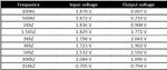
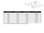
I have built this high pass filter on a bread board but it seems to be very unstable.
Is there any mistakes on the circuit
 

Not shown in the schematic, but you have built the circuit with single supply, R1 connected to OP negative supply. This doesn't work. If dual supply isn't an option, you can use a 2x20k voltage divider between V+ and V- in place of R1.
 

of course a op amp needs a dual supply DOH!!!

Is anyone kind enough to do a schematic for dual supply? or where do I put the +/-
 

Hey I'm not an analog guy (I work on FPGAs), but this is a that doesn't have any filter circuits!
 

ANY opamp works from a single polarity supply if its input is biased at about half the supply voltage.
 

of course a op amp needs a dual supply DOH!!!

Is anyone kind enough to do a schematic for dual supply? or where do I put the +/-


Take a look at the datasheet. It will clearly state which pins are for V+ and V-.

Don't feel too bad. I remember [many years ago] a popular electronics magazine publishing a circuit. Many readers wrote in, complaining it did not work. The reason was that the V+ and V- were not shown on the schematic, and readers had not attached a power supply!!!
 

You just connect half of the supply voltage instead of ground at R1. That should work
 
  • Like
Reactions: Dont

    Dont

    Points: 2
    Helpful Answer Positive Rating
Pin 7 is +v and pin 4 is -v.

8 is the NC
 

Can anyone design this circuit in a breadboard for me :).
Struggling at the moment can't seem to get a out put
 

I believe the single supply circuit has been suggested in post #2 and #8.
 

Thanks.

I have some results.

How do I work the gain out :-S
 

Attachments

  • test.jpg
    test.jpg
    63.3 KB · Views: 72

The gain is +1 by design, but with passband ripple according to your selected (Chebychev, about 1.2 dB) filter characteristic.
 

The input and output signal levels drop when the frequency increases. Why?
How are you measuring the signal levels? A cheap multimeter is accurate only at 50Hz and 60Hz then its reading drops at higher frequencies.

The gain of this circuit is 1 because the opamp is a follower with a gain of 1. If the gain is increased to about 1.25 then it peaks at the cutoff frequency and if the gain is higher than about 1.6 then it oscillates. The ratio of the two capacitor values affects peaking or oscillation when the opamp gain is increased. Add another opamp if you want some gain.
 

I was using a cheap multimeter yes.
 
Last edited:

You do not need to work out the gain or loss at each frequency. It is second order highpass filter so its output drops -12dB (to one-quarter) for each octave (half the frequency).
At 1500Hz its output is -3dB (0.707 times) of frequencies when its output levels are flat.
Then at 750Hz its output is 1/4 of frequencies when its output levels are flat.
Then at 375Hz its output is 1/16th.
Then at 187.5Hz its output is 1/64th.
Then at 93.75Hz its output is 1/256th (if the input is 2V then the output is 0.0078V). The gain (loss) is 12dB + 12dB + 12dB + 12dB= -48dB.

Get a better multimeter, an audio mV meter or oscilloscope.
 

test.jpg


Needs to be like this example, so I can plot a graph
 

Attachments

  • u2-p8-high-pass-filter-circuit-3-638.jpg
    u2-p8-high-pass-filter-circuit-3-638.jpg
    43.9 KB · Views: 73

The gain of this circuit is 1 because the opamp is a follower with a gain of 1. If the gain is increased to about 1.25 then it peaks at the cutoff frequency and if the gain is higher than about 1.6 then it oscillates. The ratio of the two capacitor values affects peaking or oscillation when the opamp gain is increased.
You can actually achieve any filter Q and respective peaking in the Sallen Key topology with gain = 1.
 

Okay all sorted.

Now how do I work out the critical frequency
?
 

Now how do I work out the critical frequency?
What is a "critical frequency"? Highpass and lowpass filters have a "cutoff frequency" where it is just beginning to filter and the output level is -3dB from the input level.
Look in Google for this type of filter called Sallen-Key Filter and you will see many articles showing the equations.
 

Status
Not open for further replies.

Similar threads

Part and Inventory Search

Welcome to EDABoard.com

Sponsor

Back
Top