Continue to Site

Welcome to EDAboard.com

Welcome to our site! EDAboard.com is an international Electronics Discussion Forum focused on EDA software, circuits, schematics, books, theory, papers, asic, pld, 8051, DSP, Network, RF, Analog Design, PCB, Service Manuals... and a whole lot more! To participate you need to register. Registration is free. Click here to register now.

High output voltage (output from power inverter)

Status
Not open for further replies.

magicbrainz

Newbie level 5
Joined
Oct 10, 2017
Messages
9
Helped
0
Reputation
0
Reaction score
0
Trophy points
1
Activity points
71
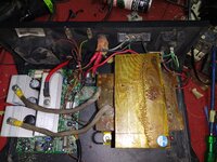
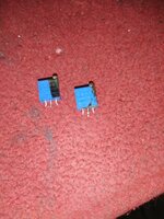
Good day, please I have this smiley su-kam 1.4KVa inverter showing high voltage output @ 280v. Even on load the voltage is still 280v. I tried varying the two potentiometer on the PCB, no change was noticed, I even went ahead to change the PT but all still the same. What is the possible cause and solution for it. Thanks.
 

Attachments

  • IMG_20210515_180138.jpg
    IMG_20210515_180138.jpg
    6.1 MB · Views: 218
  • IMG_20210515_112510.jpg
    IMG_20210515_112510.jpg
    2.1 MB · Views: 218

Some types of power inverters put out a waveform that causes odd readings on ordinary voltmeters. Is your inverter a sinewave type? Or does it produce square waves or 'modified sine waves'?
 

1.
Those look like multi-turn potentiometers you removed. What is the story about them? Did you replace them?

2.
Your photograph shows 2 capacitors that appear to have white crust. It's typical of seepage due to aging or high temperatures. (The caps look like electrolytic type between large heat sinks.) Can you test them out of circuit to make sure they're good?

3.
This is a guess on my part, that switched PWM goes into the transformer primary. You report 280 VAC output voltage, load or no load. (Probably the maximum unregulated.) We can assume the switching transistors are working. The board has several IC's which probably control regulation (one IC is labelled 'Sine'). We cannot tell if an IC is bad just by looking at it, and they're nearly impossible to test individually. If you find a component which looks burned, you might replace it and if you're lucky that fixes it. Or if you have experience with such equipment then you might construct a PWM control circuit that lets you adjust duty cycle.
 

Status
Not open for further replies.

Part and Inventory Search

Welcome to EDABoard.com

Sponsor

Back
Top