Continue to Site

Welcome to EDAboard.com

Welcome to our site! EDAboard.com is an international Electronics Discussion Forum focused on EDA software, circuits, schematics, books, theory, papers, asic, pld, 8051, DSP, Network, RF, Analog Design, PCB, Service Manuals... and a whole lot more! To participate you need to register. Registration is free. Click here to register now.

High- or low-side current sensing for the Li battery?

Status
Not open for further replies.

kender

Advanced Member level 4
Joined
Jun 19, 2005
Messages
1,425
Helped
138
Reputation
276
Reaction score
39
Trophy points
1,328
Location
Stanford, SF Bay Peninsula, California, Earth, Sol
Activity points
10,035
low side current sensing

Colleagues,

I’m designing a system that will have a Li battery and a linear charger for it. I want to measure charge and discharge currents to estimate the run time for my system. Is there a fundamental difference between high- and low-side current sensing?

Any relevant insights and references are appreciated!

Sincerely,
Nick
 

low side current sense

Hi, charge current will drop if the battery reaches full capacity. Because of this it will be necessary to provide power to the load from an other supply. If you don't do this, the load will clamp the battery voltage at a voltage of say 3.5V. Not that much below 3.6V, but your battery will be charged for 80% at 3.5V. So, basically it will require two current sense resistors. I would go for high side current sensing based on a ZXCT1009. This devices can be switched off by disconnecting the Iout pin with a BC807 or something alike.


Regards
 

li-battery protection

Hi, one in series with the charger. And one in series with the load. Both high side of course. I think you will understand if you look at the ZXCT1009 data sheet. If not, let me know. I will try to post a schematic including the shutdown option. Next week I will be very busy. It might take a few days before I can send a reply.

Regards
 

battery side current

To make accurate estimations of current I'll also need a voltage reference, because V(I) will be absolute (as opposed to ratiometric). I'll probably use a single current sense resistor with a bidirectional MAX4071, because the latter has an on-board voltage reference. That way I'll replace 3x SOT-23-3 chips (a pair of ZXCY1009 and a voltage reference) with one uMax-8.
 

current sense charger low side

Is there a fundamental difference between high- and low-side current sensing?
If you have a digital interface to any host you need low-side resistor with high-side protection transistors. Any notebook battery pack uses this aproach.
 

For that purposes we have used BQ26220. It uses only a current mesuring resistor placed at the low side. It provides chargue an dischargue measurements, sensign current sign.
 

The MAX4071 seems a good idea. I haven't seen that device. Thanks for bringing it to my attention.

Added after 1 minutes:

Fom, why would one need low side sensing if you have a digital interface to any host?
 

Frankly speaking sensing resistor can be anywhere. But protection transistors should be high-side, because if they will be low-side your digital interface disappears when protection transistors will be switched OFF (no common ground). But usually sense resistor and protection transistors use opposite side. So that's why I said that.
 

i've finished a project on li-on battery charging IC.
you can call me by MSN:hjs_1982@hotmail.com

maybe we can discuss on it
I hope i can help you
 

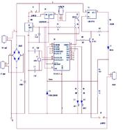
I found this circuit in the website...anyone can help to to explain about it.....thanks....


I can't read the circuit very well bu from the layout, I can give you a bit of a description on what's going on.

Top right corner is an LM317 (LM117) adjustable regulator used in it's constant current mode which is set by R2 & R8(cant read it very well)
The regulator in this mode will NOT deliver any more current to the battery (via D1) even if the the input volatge varies. (but it MUST remain at least 3volts above the maximum battery voltage) You will have to read the LM317 data sheet to understand this) Thats section 1

Section 2. The Micro
The Micro looks like it's monitoring the battery voltage at input (pin 18). This voltage is reduced to a leagal <5V for the micro input by R1 and whatever that resistor is above it and the zener diode
The micro looks like is uses the two LEDs to indicate the state of charge of the battery only.

U6 is a voltage regulator that controls the voltage for the fan alone. RB3 controls the fan ON / Off state via Q2 and R9 (i think)

The regulator to the left and below U6 is a regulator that supplies the micro with a regulated voltage (probably 5V)

That's pretty much It. !

Hope that explains it a bit.

Deanus
 

Status
Not open for further replies.

Similar threads

Part and Inventory Search

Welcome to EDABoard.com

Sponsor

Back
Top