Continue to Site

Welcome to EDAboard.com

Welcome to our site! EDAboard.com is an international Electronics Discussion Forum focused on EDA software, circuits, schematics, books, theory, papers, asic, pld, 8051, DSP, Network, RF, Analog Design, PCB, Service Manuals... and a whole lot more! To participate you need to register. Registration is free. Click here to register now.

High Noise Figure due to bad return loss?

Status
Not open for further replies.

Hi-Tone

Member level 1
Joined
Nov 23, 2010
Messages
32
Helped
2
Reputation
4
Reaction score
2
Trophy points
1,288
Location
Copenhagen, Denmark
Activity points
1,501
Hi.

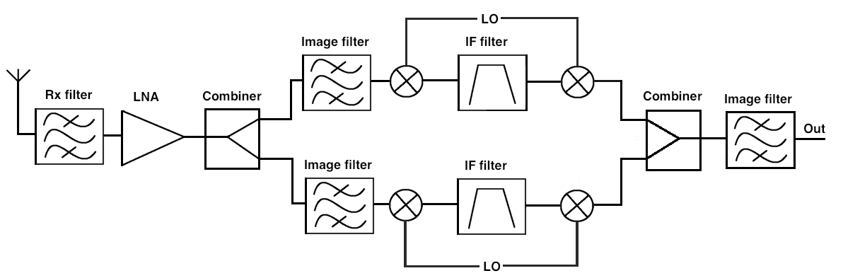
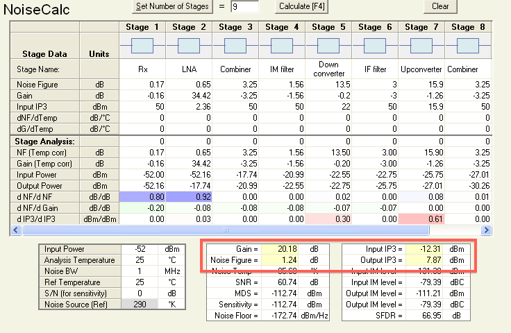
I have an AppCad simulated system with Noise Figure of 1.30 dB. The simulation doesn't consider return loss (or the return loss is seen as infinite). Now, when I measure the system I get:

Noise Figure = 4 dB.
Input return loss = 12.5 dB.
Output return loss = 8 dB.

Could my VERY high noise figure of 4 dB be because my input/output return loss is bad? or does the return loss not affect the noise figure at all?

Thanks a lot, I really appreciate it.
 

I don't think so, it seems your return loss is good, though not so good. So there is some other points increasing the NF. If you could post your system, we can give more advice.
 

Hi tony.
Thanks for helping. Here are my files:


The system is a channelized TMA with 2 channels. Here is what i got so far:
- If LO from channel 2 is off, I get 4 dB NF on my output.
- If Channel 2 is taken out of the system and replaced by two 50 ohm loads at each combiner, I still get 2.5 dB NF on my output.

In both cases i suspect that the NF should be 1.30 as simulated. All simulated values comes from measurements of each component.
 

1. It seems the isolation of the combiner is not so good. And the VSWR of the filter after the 1st combiner is not so good, or the two filter interactive each other at the combiner. Try to add 3dB PAD for each branch after the 1st combiner.
2. I think it's better to filter after the 2nd mixer, then combining.
3. You can test each component specification. If all of them are OK, then it should be VSWR problem. Try to add isolator at some points.
 
1. The isolation between the two channeling ports of both combiners is around 30 dB. It's a 3 dB wilkinson combiner. Isolation image below. I could try pads. The return loss of all the image filters is around 8.5 dB = VSWR of 2.19. I could try and remove them to see if there is any impact.
2. I could try and do that that to.

Another strange thing occurred when I did measurements. If I remove the IF filter (the filter between the mixers) I remove around 1.5 dB NF. The VSWR of the IF filters is 1.2. How can that be when the return loss of the filters are so good?


Thanks for all the help.
 

Because the gain of your circuit after the LNA is not high (actually you have only losses components), whatever change in NF or loss you get after the LNA the total NF of the system would not change too much.
In this situation the only major contributors to the total NF are the loss of the RX filter (one-to-one in dB to the system NF), and the NF of the LNA (degradation to 3.55dB NF to get 4dB system NF).

There is a possibility when you connect the RX filter to the LNA, you shift the gamma optimum NF matching of the LNA (degrading its NF).
Also is possible, you measured the insertion loss of the RX filter using 50 ohms at the output, but when it see the complex impedance of the input of the LNA, the filter loss to go higher, degrading in this way the system NF.

In the real life have to tune the LNA input for best system NF, with the RX filter and LNA connected together.
 
Thank for helping, but the Rx filter and the LNA is not the problem at all and gives me 0.8 in NF and gain of 34. The problems is as described in my previous posts.
Does anyone have any idea of what the issues is with that IF filter?

Thank you.
 

Try to change the filter specs in order to change the NF of the system
 

Status
Not open for further replies.

Part and Inventory Search

Welcome to EDABoard.com

Sponsor

Back
Top