Continue to Site

Welcome to EDAboard.com

Welcome to our site! EDAboard.com is an international Electronics Discussion Forum focused on EDA software, circuits, schematics, books, theory, papers, asic, pld, 8051, DSP, Network, RF, Analog Design, PCB, Service Manuals... and a whole lot more! To participate you need to register. Registration is free. Click here to register now.

High Impedance to 50 ohm

Status
Not open for further replies.

spanky3311331333

Newbie level 3
Joined
Jun 24, 2011
Messages
4
Helped
0
Reputation
0
Reaction score
0
Trophy points
1,281
Location
East Coast
Activity points
1,319
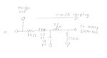
I've been going around in circles for a little while trying to figure out how to design my rf detector circuit. Here is what I have:

RF signal (10 MHz) that is going to the external world at 50 ohm impedance. I want to tap off this at high impedance to a low pass filter (butterworth) then to an rf detector IC (MAX9932EUA+ or LTC5507ES6#TRMPBF).

My question is if I've tapped off at high impedance and say the power level in dBm is in reference to 50 ohm load impedance won't my dBm measurement be skewed? Would this be a true statement then; The high impedance tap only allows so much current and loading with 50 ohms will not do much because only so much current is available from the signal.

I'm trying to stay away from directional couplers and op-amps, however if needed I guess I could go with an op-amp follower circuit after the LPF, right?

Thanks for help in advance.
 

I don't understand the purpose of a lowpass filter in front of the RF detector, but you obviously would need a buffer amplifier to tap the signal without disturbing it.
 

I forget the detail where along with the 10 MHz signal there is other frequency modulated signals that must be removed. I only want to test the power of 10 MHz and below.
 

The words you are using "tap off at high impedance" do not mean much to us. Would you care to sketch up a simple block diagram or schematic of what you are trying to do.
 

It would be sort of an AGC with a filter? Attached is the pdf let me know if anything else would help. I'm guessing I will probably use a directional coupler, however most spec 10dB loss which would not be ideal if I wanted to get the actual output power. ( I could add 10dB in the MCU, but again not ideal).

Very new to RF thanks for your help.

View attachment agc.pdf
 

You cannot connect a filter with 50 Ohm input impedance at the output.
Instead, you should use a directional coupler and you have to tap-off your signal to be measured from this coupler's coupled output and then you can add this attenuation level and make calibartion.
In this case you may connect your LPF and then detector circuit.But don't forget, tapped-off output of a directional coupler frequency response is not very flat that's why you should create a calibration
routine to get the right power.
Why you wanna use a LPF ?? you want to measure the RF power below 10MHz ?? It doesn't make sense..
If you would measure whole spectrum, you don't need to put a LPF, detector will probably work at that whole spectrum and its output will be DC but frequency response will be variable and you should also calibrate this output with a well known reference..
 

interesting problem. Normally you would use a directional coupler, possibly 10 or 20 dB, and sample off the 10 mhz signal. But a directional coupler that works well at 10 MHz would probably screw up the 900 mhz signal (too big of a % bandwidth). So I would just use a resistive probe, like a 470 ohm series resistor coming from the output connector center pin, followed by a 50 ohm shunt resistor right at the lpf input. IF the output load is relatively matched and stable, you will have a fairly constant sampled power. You just have to calibrate your power detector once, after that it will work with the same coupling factor.
 
In Mini-Circuits, there are many couplers that can reach as low as 5MHz, so you can select one.
**broken link removed**
 

Thanks for all the replies.

Biff- I sort of have an idea of what you are talking about, however am still sketchy on how it it may work and if it would be ideal. The output load may or may not be connected at any given time.

I've looked at Mini-circuits directional couplers and have found one I like that is rated from 50 -2000 Mhz (hoping that the graph may stay some what linear down to 10 MHz.) I do see that a coupling of 17 dB. Is this normal? My 10 Mhz signal will most likely be 0 dBm so in theory if I read -17dBm after the coupler all is well, correct? I def. new to this stuff (right out of college), so once again thanks.

I'm really starting to appreciate RF design.
 

I recommend you use coupler that can work 10M and the other freq.

Yes, you are right at -17dBm
 

Go with Tony_lths approach. I did not know you could get such a broadband coupler so easily.

If you want to build your own, here is a sampler that will pass only the 10 mhz to the detector port at 10 dB down, and pass the 900 and 10 mhz signal to the combined output port.

Rich
 

Attachments

  • sampler.jpg
    sampler.jpg
    51.6 KB · Views: 133
Last edited by a moderator:
Status
Not open for further replies.

Part and Inventory Search

Welcome to EDABoard.com

Sponsor

Back
Top