natmag
Newbie level 5
Hi,
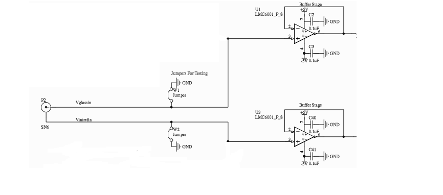
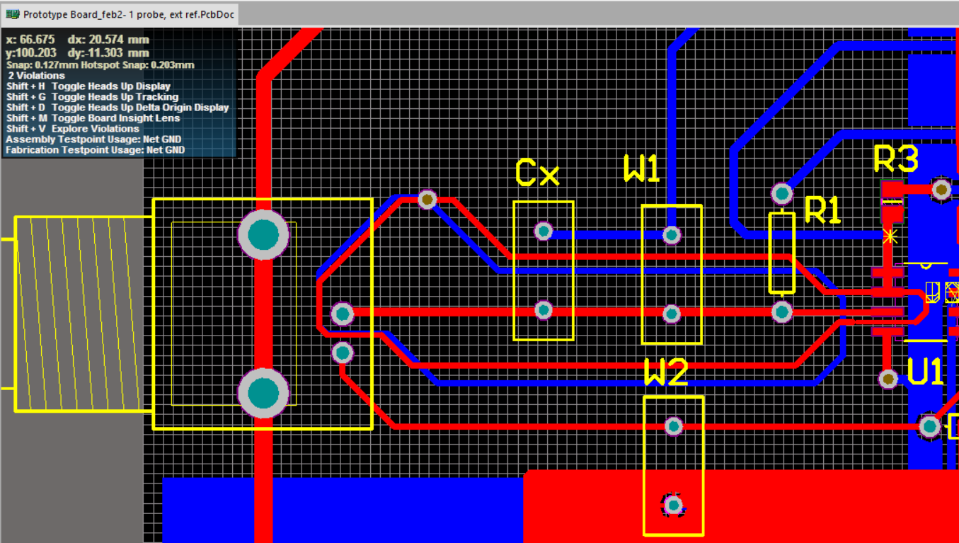
I am trying to interface a high impedance pH electrode using an LMC6462 op-amp. The LMC6462 op-amp is a high impedance op-amp with an input bias current of 150fA. The input pin of this op-amp is surrounded with a guard ring such that the op-amp is guarded from any leakages and supposedly the pH probe potential is measured. The circuitry is cleaned thoroughly to ensure that ESD does not effect the input stage of the opamp as well. I am having trouble in getting the necessary measurement readings. On connecting the LMC6462 op-amp to the sensor the output of the buffer saturates negatively instead of giving the required 177mV reading. It is as if the op-amp has a lower input impedance than the sensor (500M) and thus the potential measurement cannot be read. This result occurred even when the op-amp was changed.
How can one please avoid this from happening and guard the LMC6462 input stage? Please help ...how can I measure from such a high impedance sensor?
Thanks