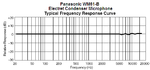
Continue to Site

Welcome to EDAboard.com

Welcome to our site! EDAboard.com is an international Electronics Discussion Forum focused on EDA software, circuits, schematics, books, theory, papers, asic, pld, 8051, DSP, Network, RF, Analog Design, PCB, Service Manuals... and a whole lot more! To participate you need to register. Registration is free. Click here to register now.

High gain microphone pre amplifier circuit, where would the bottlenecks be?

Status
Not open for further replies.
So what about the microphone itself? I'm thinking that something in my circuit is filtering out high frequencies since it goes off easily by a weak hum, but flicking my fingers doesn't (even though the flicking is fare more audible). I know that the human ear is far more sensitive to frequencies in the 3khz region, but still. The only low-pass filter I can find is the GBP, but with a gain of 300, the cut-off should be about 20khz. The mic I'm using now has a 20-15khz response, I could at least get one with a 20khz response. I'm looking at mics at mouser's website, but there's an ocean of them and I'm not sure what to look for. Is the S/N ratio parameter something to take into consideration for this application perhaps? I don't know much about these electret mics and their parameters :(
 

Since the opamp is wrongly made inverting with a low input resistance of only 1k ohms then its gain is 300 only when fed from a source with a very low resistance. But an electret mic is not a low resistance, it is about 2.5k ohms which in series with the 1k input in your circuit causes a 300k to 3.5k divider which produces a gain of 86.

C7 cuts high frequencies and if the diode is a 60Hz rectifier then it might also cut high frequencies. All the very cheap electret mics I have seen produce excellent high frequency response and low noise.
Here is the frequency response graph of an ordinary electret mic:
 

Attachments

  • Electret microphone.PNG
    Electret microphone.PNG
    16.8 KB · Views: 71

C7 is not present.

I see now how the gain is reduced by my design :( But wouldn't increasing the feedback resistor to 1M do the same trick as using a non-inverting design, gain wise I mean?
 

When the feedback resistor is 1M then some stray capacitance of only 20pF cuts frequencies of 8kHz and up.
Use the inverting opamp circuit with a 600 ohms dynamic mic (coil and magnet) but use a non-inverting opamp circuit for an electret mic.
 
Status
Not open for further replies.

Similar threads

Part and Inventory Search

Welcome to EDABoard.com

Sponsor

Back
Top