Continue to Site

Welcome to EDAboard.com

Welcome to our site! EDAboard.com is an international Electronics Discussion Forum focused on EDA software, circuits, schematics, books, theory, papers, asic, pld, 8051, DSP, Network, RF, Analog Design, PCB, Service Manuals... and a whole lot more! To participate you need to register. Registration is free. Click here to register now.

High dynamic range HF preamp help

Status
Not open for further replies.

neazoi

Advanced Member level 6
Joined
Jan 5, 2008
Messages
4,122
Helped
13
Reputation
26
Reaction score
15
Trophy points
1,318
Location
Greece
Activity points
36,951
Hi I have built this little 40m HAM band receiver and I notice sometimes that signals from commercial broadcast bands can be heard. I am mostly sure it is caused by some king of intermodulation, due to the low dynamic range of the unfiltered broadband preamp.

So I would like to test the receiver with a high dynamic range preamplifier.
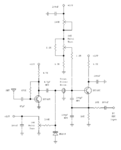
One design I like, because of it's simplicity, is this one
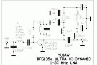


from this page
https://www.qsl.net/yu1aw/LNA/bfg135aeng.htm

I would like to do some modifications to it.
I calculate that the input inductor is about 85nH. I have molded chokes of 100nH. Can I use them in place? My simulation on this "filter" show no significant alteration of the input filtering, with this modification. After all it seems it is used there to slowly and gradually attenuate the >100MHz frequencies.

Also what If I want to power it from a 12v battery without the 7810 regulator? how should I modify it?
 

Attachments

  • Capture.PNG
    Capture.PNG
    20.3 KB · Views: 147
Last edited by a moderator:

Yes, should be OK to use chokes in this case as they don't seem to be part of a high Q network.
 
  • Like
Reactions: neazoi

    neazoi

    Points: 2
    Helpful Answer Positive Rating
Yes, should be OK to use chokes in this case as they don't seem to be part of a high Q network.

Thanks.
What If I want to power it from a 12v psu without the 7810 regulator? how should I modify it's power network?

I will remove the regulator, the choke near it and it's two shunt capacitors, but which value of resistor should I use instead of the 33R?
 

Thanks.
What If I want to power it from a 12v psu without the 7810 regulator? how should I modify it's power network?

I will remove the regulator, the choke near it and it's two shunt capacitors, but which value of resistor should I use instead of the 33R?
You can keep the 33ohm resistor even if powered from 12V.
It is probably a good idea to keep one of the larger caps even if you remove the 7810.

//Harry
 
  • Like
Reactions: neazoi

    neazoi

    Points: 2
    Helpful Answer Positive Rating
You can keep the 33ohm resistor even if powered from 12V.
It is probably a good idea to keep one of the larger caps even if you remove the 7810.

//Harry

I worry about the IMD products, since the author has simulated it at 8v and IC=60mA as it is shown in the schematic. However he uses a 10v regulator, which is a bit confusing.
If using the same 33R load resistor, won't the current be larger at 12v? This might have an impact on the IMD.
 

The 33ohm resistor only very marginally affects the collector current. Its the feed back resistors that controls it.
The 33ohm resistor is a low pass filter with the 1nF C and the 100uH L.
This low pass filter provides stability to the circuit to avoid oscillation, the value is most likely not critical and anything between 10 ohm to 100 ohm would probably be equally fine.

Thanks for the reply.

I wonder if one wants to try a coil-less design, couldn't he replace the input coil with an RC filter and the power intuctor with an RC filter as well?
I guess some gain will be lost, but this device has plenty of gain eitherway.
 

Thanks for the reply.

I wonder if one wants to try a coil-less design, couldn't he replace the input coil with an RC filter and the power intuctor with an RC filter as well?
I guess some gain will be lost, but this device has plenty of gain eitherway.

The input LC components and values are vital as they match the 50 ohm input impedance to the impedance of the transistor stage.
Get it wrong and you can easily loose 20 or 30 dB of gain, e.g. you will have a fine attenuator instead of an amplifier :).
The output L is less critical and can be a molded choke so it should present less of a problem as you do not need to hand wound it.

So the VALUE of the input coil is critical? This comes in contrast to what you have said on post #2.

The calculated value of the original indictor is about 85nH, and the chokes I have available are a bit more, 100nH.
 

In post #2 I was referring to the two chokes on the output side.
The input L is critical and can not be a choke. It has to be hand wound to get a high Q inductor.
The best would be to use the same wire diameter as the designer so as to be sure to get the correct inductance and Q.
But if you have a LC meter you can wound something simular and measure it and then adjust the turns by spreading them or compressing the turns so you arrive at the correct value.
But stay away from chokes for this L as they are very low Q and will not do the job in the input circuit.

Thank you!
My chokes are EPCOS and have a ceramic core not a ferrite.
I expect their Q to be a bit higher for that reason but I am not sure anyway.
 

Status
Not open for further replies.

Part and Inventory Search

Welcome to EDABoard.com

Sponsor

Back
Top