Continue to Site

Welcome to EDAboard.com

Welcome to our site! EDAboard.com is an international Electronics Discussion Forum focused on EDA software, circuits, schematics, books, theory, papers, asic, pld, 8051, DSP, Network, RF, Analog Design, PCB, Service Manuals... and a whole lot more! To participate you need to register. Registration is free. Click here to register now.

High Current Regulators

Status
Not open for further replies.

very

Newbie level 5
Joined
Feb 20, 2009
Messages
9
Helped
1
Reputation
2
Reaction score
1
Trophy points
1,283
Activity points
1,364
I have designed many working circuits by using parallel regulator devices.

I would like to know why single high current regulators like LM1084 do not meet their specs of 5A. Poor regulation after 2A. I am using a large Transformer-Bridge Rectifier-Smoothing capacitor combination and NS suggested circuit. Huge heat sinks. LM317 appears to fare slightly better.

Thanks
 

Incorrect usage of the device would be my first guess: input voltage too high, input voltage too low, insufficient bypassing, thermal overload.
 
Thermal issues would be my guess. Even a few watts of dissipation with a large heatsink can cause a 20C rise in die temperature, which is enough to cause noticeable errors. What kind of regulation are you seeing?
 
The regulation can be as bad as 50%. Just above 2A it is 20%.

I have found that LM350 in the same circuit gives better regulation though still no where near NS specification. Can be a thermal issue but I have used a massive heatsink - also a fan - nothing more can be done. I wonder whether driving the control pin by another device might help? That ofcourse defeats the purpose of a single device regulator.

Back to 2N3055s in parallel and darlingtons I suppose.

I am just curious why these single devices (LM1085, LM1084) do not work well.
 

Don't neglect wiring drops or ground rise. Anything outside
the Kelvin return / sense points is on you, part knows
nothing. There must be some ideal hardware condition
where the parts meet spec. Look at their eval board
layout and you'll see what that is, and then think about
how your reality differs.
 

I'm very surprised at these poor results.

Could you advise what ripple you are seeing at the input? - the minimum & maximum instantaneous input voltages?
Does this maintain the device's minimum drop out voltage at absolutely all times?
Have you created a 'star' for the grounds, keeping sense/reference grounds clear of all current-carrying grounds & the main capacitors' grounds?
Included some low-resistance High-frequency caps close to the regulator?
Included a cap on the 'ground' leg of the reg if there's also any resistance on the 'ground' leg (in parallel)?
Complied with the manufacturer's recommendation of using low ESR input caps and even multiple output caps?

You should be able to achieve much better regulation than that. You'll find the reason soon enough!

(I'd be tempted to reach for the can of 'Freezit' at this point, and when really desperate, I'd even spray the caps too!)
 
Last edited:

I am surprised at these results as well hence looking for answers here.

Have used a huge transformer, thick wires, allowed at least 6V drop minimum across the regulator device at full load and excellent quality capacitors.

These devices have thermal shutdown if good heat sinks are not used.

Measuring voltage at the output capacitor.

I am trying to use the simple circuit given by NS - a resistor and pot.

Can someone try this device and circuit as per NS data sheet and post results here please?
 
I guess, there won't be that much people using these devices. Mainly because high current has become a domain of switching regulators since long.

Nevertheless I'm quite sure, that the reason for design failure can be identified by measurements in your setup. I don't know, if it's obvious or hidden. But I didn't yet hear about quantitative results, neither DC measurements nor oscilloscope waveforms. I can't imagine that somebody is motivated to spend time on the issue without getting some more information first.
 

@very
Thanks for answering a couple of my questions about your circuit, particularly answering :
Included a cap on the 'ground' leg of the reg if there's also any resistance on the 'ground' leg (in parallel)?
with this reply :
I am trying to use the simple circuit given by NS - a resistor and pot.
You'll see in the NS Datasheet two example circuits which include a cap of 10uF between ground and the the 'ground' leg which are specifically shown 'for improved ripple rejection'. "Xc SHOULD = R1 AT RIPPLE FREQUENCY" (That was why I asked, and I recommend using these caps to you).

My other suggestions were also based on the manufacturer's data and/or experience, and remain unanswered. These were :
Have you created a 'star' for the grounds, keeping sense/reference grounds clear of all current-carrying grounds & the main capacitors' grounds?
Included some low-resistance High-frequency caps close to the regulator?
Complied with the manufacturer's recommendation of using low ESR input caps and even multiple output caps?
It appears to me that dick_freebird's advice to consider and eliminate wiring losses in the grounds was very well aimed.
Don't neglect wiring drops or ground rise. Anything outside the Kelvin return / sense points is on you, part knows nothing.
Perhaps more precise measurement data, component values and an image showing the layout would help us?
I guess, there won't be that much people using these devices. Mainly because high current has become a domain of switching regulators since long.
Maybe so, but we still have such PSUs on our bench quite regularly!
 
Last edited:

Thanks for trying to solve this tricky issue.

I have used star topology for grounding. Anyhow I have used thick (30A) wires so wire resistance is not the problem. Also I am measuring voltages at the output pin of the device. There are two more 10mF capacitors at the input and output pins of the device (as per NS circuit) in addition to two 0.1mF ceramic.

Removing the transformer - bridge- large smoothing capacitor combination and getting the input from another high current stabilised supply did nothing to improve the regulation. So it is not a ripple problem.

However when I connect a fixed voltage regulator like LM1084-3.3 I have no problem with regulation at higher currents.

Only in the variable output voltage device that this problem appears. The two resistors outside for the variable device are moved inside the device for the fixed regulator.

It could be that I might have got my devices off a particularly bad batch.

Linear regulators are more reliable and noise much less of a problem. So I wish to persist with this design.
 

Is the return-point for your feedback resistor divider, the
right one? Kelvin connected to the regulator ground and
not offset by I*R in the power return?

If you are AC-unstable then you may want some
feedforward capacitance from the load. But poor DC
load regulation has to be some I*R, somewhere.
 

    V

    Points: 2
    Helpful Answer Positive Rating
It could be that I might have got my devices off a particularly bad batch.
Possible, but unless you have reason to suspect . . . then unlikely. One device, yes, a batch, no.

Linear regulators are more reliable and noise much less of a problem. So I wish to persist with this design.
I strongly agree with you and wish I had one in the bucket of regs to try myself to reproduce your findings. (I'd be pleased to if I had - out of sheer interest!).

However, I'm only able to help with the perverse logic of a critical friend (which is where these agressive & challenging questions come from) :-
Did you put a cap between 0v and the device's 'ground' terminal and is that grounded only to the star point?
Have you applied coolant spays whilst watching the 'scope?
Have you been able to measure temps at localised points?
Have you experminted by moving earthing points between the star position and their local ground?

Yes, I know an experienced engineer calculates rather than randomly probing and swapping, but I'm assuming that you're at the stage where the calc.s are not helping. You either re-calculate ABSOLUTELY everything and assuming nothing, get desperate and start swapping and bodging things, or you express your frustratiopn on a global internet forum. So lets all get desperate and 'assume nothing' together.
Check everything three times and give us the empirical results - we're here to help.
 

wish I had one in the bucket of regs to try myself to reproduce your findings
I fear, no exact finding have been reported, strictly spoken. I believe, that bad regulation is seen somehow. But the repeated suggestions of placing capacitors here and there already clarify, that nobody knows, if it's an AC (stability) or a "simple" DC problem. But it can be clearly distinguished. Also the measured regulator pin-to-pin voltages under "bad regulation" conditions have never been told (as DC+AC measurements). So my initial guess about "incorrect usage of the device" hasn't been disproved yet.
 

Again, thanks to DXNewcastle, FvM and all for being intrigued like myself, about this one off tricky problem.

Yes I applied coolant spray. When I had smaller heat sink the cooling prevented thermal shutdown. When I switched to the huge heat sink spraying had no effect on load regulation, ripple etc.

I have tried floating the 0V, earthing it and tried different star comination. Tried to connect the divider/sensor resistors near the load as well, but as I had thick wires it had no effect. There is no voltage drop anywhere other than across the device, meaning the device is not regulating. Ripple in few millivolts too.

I have followed NS suggested circuit faithfully. I have designed 10A ones previously but used cumbersome discrete devices. Have used many 78XX and 79XX devices with no problem.

Not sure what is meant by putting a capacitor between device ground and 0V. Could you suggest a circuit please (DXNewcastle)?

Obviously, the ideal solution is for someone to try the device. I intend waiting for few weeks and get a different device (hopefully different batch).
 

Not sure what is meant by putting a capacitor between device ground and 0V. Could you suggest a circuit please (DXNewcastle)?
From **broken link removed** I see the text advises a cap between the 'ground' pin and circuit 0v which is illustrated with C1 = R1 at ripple frequency thus:-
PSU reg LM1084.gif
The datasheet further explains the current flowing from the 'ground' pin and its dependence on Load and on Temperature.
Pages 7, 8 and 9 of the datasheet contain more practical and numerical advice regarding load regulation, ripple rejection, and thermal performance. These should be of some assistance and it is those notes that have informed some of my questions to you.
 

Just floating ideas...

The data sheet describes it as being a 'low drop out' regulator.

**broken link removed**

One of the issues you get into with such a device is that effectively the device controls output current and therefore the voltage loop gain is very dependent on the load.

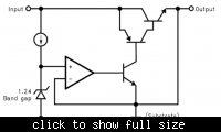
Given the output structure as indicated by,


I don't think this qualifies as a 'low dropout' regulator. Certainly the first page states dropout is 1.5V and that, to me, is not 'low dropout'.

Unfortunately it might as well suffer from the same problems as 'real' 'low dropout' regulators do. You have a PNP transistor supplying base current to an NPN transistor, as the output device.

Effectively that means that the combined structure is a current source and therefore the output voltage is dependant on the load impedance.

As an aside you need 2 Vbe, or 1.4V, drops for the compound structure to be active which would give you the '1.5V' dropout voltage. It is not exact but if they are carrying current then your Vbe will be larger.

So, it is not low dropout and yet it is still acting as a current source and therefore the voltage gain depends on the 'load'.

They 'babble' about this on page 7) of the data sheet.

STABILITY CONSIDERATION
Stability consideration primarily concern the phase response
of the feedback loop. In order for stable operation, the loop
must maintain negative feedback. The LM1084 requires a
certain amount series resistance with capacitive loads. This
series resistance introduces a zero within the loop to in-
crease phase margin and thus increase stability. The equiva-
lent series resistance (ESR) of solid tantalum or aluminum
electrolytic capacitors is used to provide the appropriate zero
(approximately 500 kHz).

Oh, did I mention there is the possibility that the regulator is basically unstable as a result of the load. I am sure it does not help much in as much as the data sheet does not help. I see no realistic clues or guesses to that one from the information given.

I might imagine, wet finger in air, that you should ignore the 'distributed' load, given it will be 'rubbish' and concentrate on what is local to the regulator. Apparently you need an 'appropriate zero' at 500KHz. Thank you very much National Semiconductor.

I'm sure this will not work, but, but, but.... Nope, don't know. Insufficient information provided. I had 'hoped' that the 500KHz figure was, perhaps, associated with unity gain and therefore you would have a figure for ESR to achieve it.

Assuming National Semiconductor wishes to sell product that becomes their problem. Obviously they can come back and slap me but I would recommend you 'design that one out'.

Genome.
 

Sorry, yet to work out how to post quotes.

DXNewxastle: NS circuits are showing 0V as grounded, hence the capacitors are all connected with respect to 0V or ground. I have used all capacitors in the diagram. Ripple is not the problem. Your reference to Capacitor between ground pin and 0V does not make sense.

Genomerics: You are getting my drift. There appears to be something not right about this device (I have carefully said a bad batch). I am not using this device for low_drop_out reasons. Just that it is convenient for higher current. I have allowed 6V voltage drop across device at 5A and chosen the unregulated side. There is no such 500KHz 'babble' about LM150/LM350 3A devices in their data sheets - obviously a completely different device design. LM150s work OK at 2A and reasonable at 3A. LM1084 do not appear to work. I have tried to get them to work at 16V and 4V. My load is resistve. It would be so useful if they worked.
 

DXNewxastle: NS circuits are showing 0V as grounded, hence the capacitors are all connected with respect to 0V or ground. I have used all capacitors in the diagram. Ripple is not the problem. Your reference to Capacitor between ground pin and 0V does not make sense.
Please refer to schematic in my post of 25th Feb.
The 10uF cap is between the Regulator's reference pin and 0volts. Not all the applications in the NS datasheet show that capacitor; the text advises.

Further to your circuit, I understand that your circuit uses two resistors in a potential divider, their junction presumably being that Reference pin.
Note that the Regulator's output is a product of the voltage on that pin and its internal reference, but as higher currents are drawn we should expect that the internal current paths are in parallel with the upper half of that divider, which will shift the reference voltage positive and therefore reduce output current prematurely. Consequently, measures must be taken to compensate at higher currents, these might be active circuitry to derive a reference voltage which is independant of current, or it may be enough to reduce resistor values in the voltage divider to mitigate the effect of the parallel current path within the Regulator.
 

Apparently you need an 'appropriate zero' at 500KHz. Thank you very much National Semiconductor.
There is no such 500KHz 'babble' about LM150/LM350 3A devices in their data sheets - obviously a completely different device design.
The problem of needing a minimum ESR along with the output capacitor can be found with nearly any linear regulator, except for a few new designs that are explicitely said to be stable with ceramic output capacitors. As the quoted datasheet snippet clarifies, regular tantal or aluminium electrolytic capacitors will provide sufficient ESR.

The fact, that the ESR problem is emphasized in the datasheet may indicate, that LM1084 is more critical in this respect. But as I already mentioned, instability would clearly show by a considerable AC voltage level at the output. Also by a changing behaviour when bypass capacitors are added or removed.

If no other reason can be identified, we have to accept the bad batch assumption.
 

Status
Not open for further replies.

Similar threads

Part and Inventory Search

Welcome to EDABoard.com

Sponsor

Back
Top