Continue to Site

Welcome to EDAboard.com

Welcome to our site! EDAboard.com is an international Electronics Discussion Forum focused on EDA software, circuits, schematics, books, theory, papers, asic, pld, 8051, DSP, Network, RF, Analog Design, PCB, Service Manuals... and a whole lot more! To participate you need to register. Registration is free. Click here to register now.

hi need help in stepper driver

Status
Not open for further replies.
The supply of the mosfets in the project is wrong, you have used VEE which is a -5v supply, if you replace it with Vcc or any other positive supply it works fine.

Alex

hi set value of VEE is 12 v in my setting

---------- Post added at 13:04 ---------- Previous post was at 12:59 ----------

hi can i use fly back diode at output, so which diode is suitable for it can i use 1n4007(1amp) or other for high current up to 3 amp????. will schotky diode use as fly back diode for back emf protection.?????
 

Yes , there was a problem with the hex path and a had to copy the project so VEE got the default value of -5, it was 24v actually in your project.
I also noticed that your motor is connected wrong, COIL A is the left two pins and COIL B the right two pins so change your connection.
You are currently connecting two different cols to each H bridge

Alex
 

ok thnanx what about protection diode at o/p can i use schotky diode at o/p of high current capacity abt 3 amp?
 

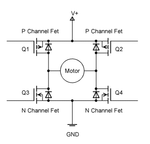
The flyback diodes are connected across the drain-source of each mosfet

Hbridge_mosfet_flyback.gif
H-Bridge_flyback2.gif

I think usually normal diodes are used.
 

ya u right i am using normal diode 1n4007 now as protection but i dont get full protection my smps get off after 2 steps of motor rotation and i thnk its due to heavy back emf of motor? so which normal diode i can use??
 

I don't think it is because of the back efm but because of the current surges of the motor coil, it is probably triggering the psu protection.

Alex
 

what i can do for that rectify alex?
 

I don't know, I haven't used a motor with a smps power supply.
Are you sure that the current rating is enough to provide the normal operation current to both coils at the same time?

Alex

---------- Post added at 11:58 ---------- Previous post was at 11:51 ----------

In your first post you said that you had a problem with the bridge operation , we didn't change anything so I don't understand how does it work now?
Have you changed anything, did you find anything wrong with your connection in the real circuit?
You didn't have this psu problem in your first post.

Alex
 

ya you are right but i change my D-filp flop with high logic o/p s so i can give exact 4v at gate to IRFZ44 and bridge is working now. but having problem mentioned in early post occurring now.so what can i do ?
 

What is the current specification of your power supply, how much current?
What is the voltage you use now for the motor, is it 12v?
What is the coil resistance of each coil, you gave a specification of 2.8A but what is the resistance?
Are you sure that the motor can work with a constant voltage or is it a low resistance motor that needs PWM to limit the current?

Alex
 

Resistance of coil is 1.13 ohm per phase . and i am using 24v/4amp power supply for motor .motor volatge is only 3.2v and i am giving 24 v to motor. ya motor need pwm i am sure
 

Yes these low resistance motors are designed to be used with pwm to limit the coil current.
You can find some stepper motors that can be used with a constant voltage (like 12v) but usually the strong motors have a low resistance.

Alex
 

so i need change my PWM frequency for rectify problem of power supply wht other solutions possible?
 

You can use a constant pwm duty ratio based on the voltage you use but the proper way is to use a feedback system that measures the current and then changes the PWM duty ratio to keep the current constant.
The variable PWM method is better because as the step speed gets higher you need to apply higher voltage (duty ratio) to the motor coil so that it keeps getting the same current.
With a constant duty ratio as the speed of the steps increases the current decreases.
You will not be able to use PWM with your circuit, you need proper mosfets drivers that can turn on/off the mosfet fast, that means high current driver.

Alex
 
Last edited:

thnx alex i will try as u suggest may it work and update u further thnx for ur help and may i need more help in this topic i update u later
 

I have also 5 phase stepper motor. Wiring diagram of the motor is star. I have search for driving that motor on Internet but I can't search. Now I am testing with totenpole connection using two irfz44n driver. That is not work well. Do everybody have any experience in driving that kind of motor? Share me knowledge.
Sincerely yours, phoeshell
 

I think you mean a unipolar motor, it has 5 wires, 1 is the common and the other four are the 4 coil sides.
It is much easier to drive than a bipolar, you don't need an H-bridge, connect the common to the positive supply and use four low side switches (uln2003, transistor, mosfet) to enable each of the coils

You can drive it with an ULN2003 or discrete transistors, check:
Stepper Motor interfacing with Microcontrollers tutorial: Step Sequence : 8051 Microcontroller Projects AVR PIC Projects Tutorials Ebooks Libraries codes
Stepper Motor interfacing with Microcontrollers tutorial: Connecting Stepper Motor : 8051 Microcontroller Projects AVR PIC Projects Tutorials Ebooks Libraries codes

Also check the drive modes Stepper motor - Wikipedia, the free encyclopedia
https://upload.wikimedia.org/wikipedia/commons/8/85/Drive.png

Alex
 
Last edited:

I think you mean a unipolar motor, it has 5 wires, 1 is the common and the other four are the 4 coil sides.
It is much easier to drive than a bipolar, you don't need an H-bridge, connect the common to the positive supply and use four low side switches (uln2003, transistor, mosfet) to enable each of the coils

You can drive it with an ULN2003 or discrete transistors, check:
Stepper Motor interfacing with Microcontrollers tutorial: Step Sequence : 8051 Microcontroller Projects AVR PIC Projects Tutorials Ebooks Libraries codes
Stepper Motor interfacing with Microcontrollers tutorial: Connecting Stepper Motor : 8051 Microcontroller Projects AVR PIC Projects Tutorials Ebooks Libraries codes

Also check the drive modes Stepper motor - Wikipedia, the free encyclopedia
https://upload.wikimedia.org/wikipedia/commons/8/85/Drive.png

Alex
Thanks for your answer, I have already drive that kind of motor but now I think my motor is not unipolar. There is no common. All resistance of pins are the same. I think the connection is star wiring. Now, I am testing by using ten irfz44 driver. I use two driver for one pin. One is for power and the other is for ground. Now, it is going to ok. Thanks for ur sharing knowledge.
 

hi alex i used high watt rating resistor at ground to h- bridge to limit the over current. but after that motor is not moving and i tried also make high PWM signal but they also don't work. can you help me out please?
 

How can you have 5 connection and no common, the coils have 2 or 2+1(middle) wires each so it should be four or six.
A unipolar can be seen as a star because you have 2 coils (4 wires) and the extra wire connects the middle point of these two coils.
If you connect 1 and 2 in the below unipolar motor you get a star
2.gif

A multimeter would show 4 small resistances from the common to the other four wires or a higher from a to a or from a to b.

Alex

Edit:
You have a 5 phase motor so what I said above doesn't apply.
5.gif
 
Last edited:

Status
Not open for further replies.

Part and Inventory Search

Welcome to EDABoard.com

Sponsor

Back
Top