ramshkrish
Member level 1
I took this board from an emergency lamp...

Follow along with the video below to see how to install our site as a web app on your home screen.
Note: This feature may not be available in some browsers.
") .. But there was already another transformer for stepping down.. why need another....??????????.. Got 4 different answers....In a HFT is there any identification for output terminal, or will i have to analyze the full circuitry...??
.. But there was already another transformer for stepping down.. why need another....??????????.. Got 4 different answers....In a HFT is there any identification for output terminal, or will i have to analyze the full circuitry...??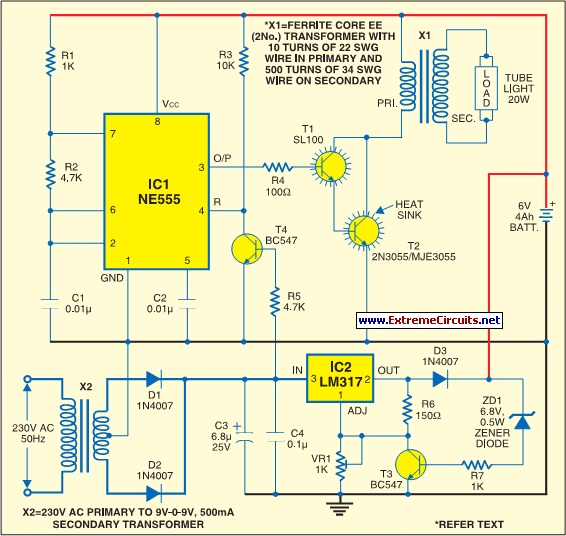 .. I was not aware that the power from the DC battery will get converted to AC before fed into the bulb...
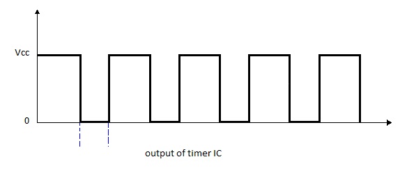
It was an old emergency lamp and I almost spent 10 years thinking that the bulb works on DC...
I would prefer to consider it as a case of AC with superimposed DC current. Interestingly, you can't know exactly about superimposed DC on the secondary because it depends on the tube's ignition voltage and transformer windings ratio. As a first guess, the secondary current will be mostly AC, when igniting the tube also in forward phase of the converter. Then a DC component will be left in the transformer's flux balance. An air gap would help to avoid saturation.The property of transformer states that a change in current in one coil induces current on the other coupled coil". The direction of current does not change that is why it cannot be said to be alternating current.