Senthilkumar_rjpm
Full Member level 2
Hi all...
some days before, For 1 of my project i needed wave form like this... (Below)
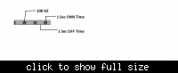
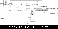
I can easily generate this wave form using this circuit (IC 4052) below...
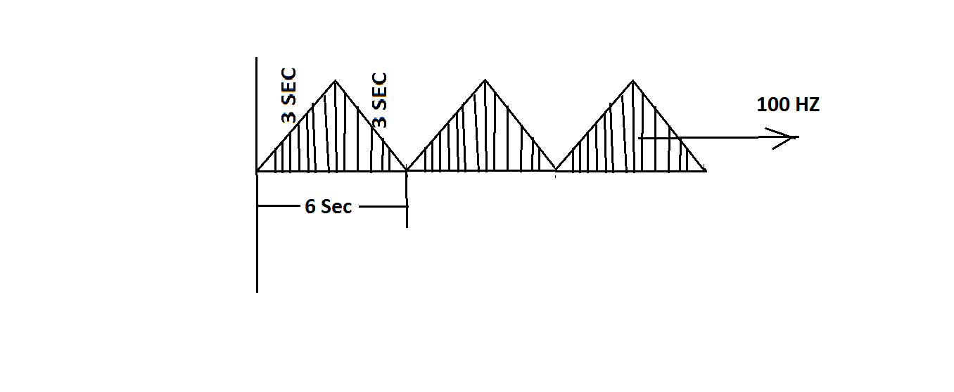
And Now the same type of project i need this type of wave form... (below)
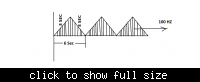
Now i didn't get any idea about to generate this wave form combination... i have a square wave with frequency of 100hz.. & Triangle wave with 3sec time delay... Now I dont know how to superimpose these 2 waveforms (Like square)?? I googled more but i didn't get any details related this...
(These types of waveform are using for treatment purpose in physiotherapy feild )
Can any one please help me how to superimpose square wave in to triangle wave...
Thanks in advance...
some days before, For 1 of my project i needed wave form like this... (Below)
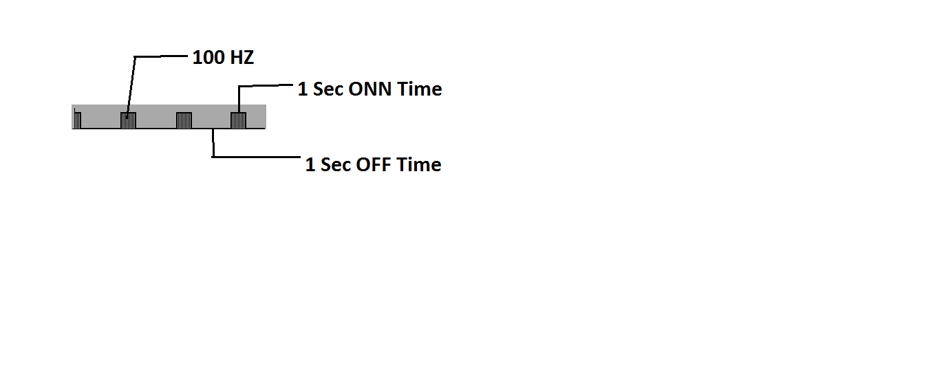
I can easily generate this wave form using this circuit (IC 4052) below...

And Now the same type of project i need this type of wave form... (below)
Now i didn't get any idea about to generate this wave form combination... i have a square wave with frequency of 100hz.. & Triangle wave with 3sec time delay... Now I dont know how to superimpose these 2 waveforms (Like square)?? I googled more but i didn't get any details related this...
(These types of waveform are using for treatment purpose in physiotherapy feild )
Can any one please help me how to superimpose square wave in to triangle wave...
Thanks in advance...

