DeboraHarry
Full Member level 5
If you use the free Antenna Design kit for HFSS it has the ability to design a number of differnt types of antennas. One antenna puzzles me though. The Quadrifilar Helix Antenna has 4 excitations. In the diagram below, the ports have been highlighted.
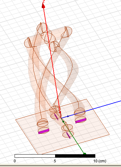
I can't see why this antenna should have 4 ports. Am I missing something?
Deborah
I can't see why this antenna should have 4 ports. Am I missing something?
Deborah