Continue to Site

Welcome to EDAboard.com

Welcome to our site! EDAboard.com is an international Electronics Discussion Forum focused on EDA software, circuits, schematics, books, theory, papers, asic, pld, 8051, DSP, Network, RF, Analog Design, PCB, Service Manuals... and a whole lot more! To participate you need to register. Registration is free. Click here to register now.

HFSS - What's best way to put multiple slots in outer conductor of coax?

Status
Not open for further replies.

DeboraHarry

Full Member level 5
Joined
Dec 3, 2011
Messages
274
Helped
48
Reputation
94
Reaction score
43
Trophy points
1,308
Location
UK
Activity points
3,905
I'm trying to model an antenna which is a bit like leaky feeder, though the aim is to make a vertical colinear, rather than the usual use of leaky feeder.

I want to create a coax from a copper tube (outer conductor) and brass rod (inner conductor). The idea is that the braid will have a number of slots, through which radiation will escape. In the diagram below, there are 4 slots, but I'd like to have 8 or more, so the radiation pattern is as omnidirectional as reasonably practical.

32_1325382756.png

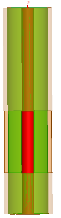
Here's an end-on view
14_1325382756.png


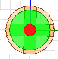
The plan would be to repeat this vertically, so a second group of 4 or 8 slots is placed some distance above the first lot.

I've defined a box and used that to cut out the slots, but are not sure how best to cut the slots out, in a way which gives me the most flexibility. Ideally I'd like to be able to change the number of slots and their positions along the coax by use of parameters. I would like to avoid being in the situation where the slots are cut, but I can't change anything easily.

In one attempt, i have a single slot and have united this with the vacuum of the airbox. But I get an error message

[error] ACIS entity check failed for part: SlotCutInCopperTube
[info] Use Modeler/Validation Settings to relax ACIS entity checking or Modeler/Model Analysis/Heal to fix check errors.


Can anyone suggest the best way to make the cuts in the coax, such that I maintain maximum flexibility? Should I unite the AirBox with the box used to create the slots? Obviously once the slots are cut in the braid and dielectric, the inner conductor will meet the airbox.

I don't know if this makes any sence.

Deborah
 

Attachments

  • Slot-Antenna-How-should-I-progress-from-here.zip
    37.7 KB · Views: 99

Deborah,

I would first try a long 4-sided box comprising my coaxial cable (filled with dielectric even) as a first iteration try (the design formulas for square coax line to determine dimensions can be found in good text books) ... I have never seen this type of antenna in commercial production, and there may be a reason for it (perhaps it does produce impractical, unusable results compared to other designs?) The box design should yield some insight as to characteristics, and if a near-real coax model is worth spending time on.

The usual coaxial-colinear design (1/2 wavelength offset pieces of coax) and even the fabricated series of dipoles with opposed or series-ed 1/4 wavelength 'choke' sections around a central core exist in the commercial antenna world, but I have not seen anything in the way of 'leaky' style radiating sections (to form a vertical 'beam'). Bear in mind the length of the slots will be kind of in accord with 'waveguide beyond cutoff' propagation phenomenon as far as allowing energy to exit and this may also impart a particular 'phase delay' onto the wave near the cutoff frequency (would be my thinking).

Jim
 
Last edited:
If I wanted to cut slots I would create an object sized and positioned where I wanted and then use the boolean operator to subtract the slot object from the tube (in your case). There are other schemes so this may not be the best but it is relatively easy to accomplish.

Azulykit
 

If I wanted to cut slots I would create an object sized and positioned where I wanted and then use the boolean operator to subtract the slot object from the tube (in your case). There are other schemes so this may not be the best but it is relatively easy to accomplish.

Azulykit

That's what I did, but at one point the box for the slots had to be united with the AirBox (where one puts the radiation boundary). Once that is done, it seems impossible to change anything, as the process of uniting has destroyed any chance of changing the number of slots. But if I don't unite them, I get errors about two intersecting objects, even though they are in fact both vacuum.

---------- Post added at 18:19 ---------- Previous post was at 18:02 ----------

Deborah,

I would first try a long 4-sided box comprising my coaxial cable (filled with dielectric even) as a first iteration try (the design formulas for square coax line to determine dimensions can be found in good text books)
But I'd still need to cut the slots, so it does not really change the situation. Cutting them in round coax is no more difficult (perhaps even easier) than square coax. My problems resolve around the issue of being able to change a design quickly, by changing a few parameters in my model. Once on starts uniting the box used to cut the slots and the Airbox with the radiation boundaries, I seem to lose that flexibility.

I have never seen this type of antenna in commercial production, and there may be a reason for it (perhaps it does produce impractical, usable results compared to other design?) The box design should yield some insight as to characteristics, and if a near-real coax model is worth spending time on.

I agree there are no commercial implementations of it, but that makes it an interesting idea for me. I can see some practical problems, but I'd like to investigate it.


The usual coaxial-colinear design (1/2 wavelength offset pieces of coax)

I assume you mean this sort of thing, first published by Wheeler in the 1950's or so.

**broken link removed**

That design I provided a link to has a vastly exaggerated gain. I think part of the issue is that the radiation from the upper sections is smaller than the lower sections, as the lower sections have already radiated power. My idea with the slots was to control the amount of power radiated.

but I have not seen anything in the way of 'leaky' style radiating sections (to form a vertical 'beam').
All the more reason to investigate it!
Bear in mind the length of the slots will be kind of in accord with 'waveguide beyond cutoff' propagation phenomenon as far as allowing energy to exit and this may also impart a particular 'phase delay' onto the wave near the cutoff frequency (would be my thinking).

Jim

Yes, I'd not considered the "waveguide beyond cutoff" issue. I was thinking that short slots would act similar to a Hertzian dipole. So I could phase a number of dipoles vertically. Idea being to control the amount of radiation from each slot by controlling the length of the slots.

You have got me thinking. Perhaps a better way to approach it is to slots with a length comparable to a half-wave, but control the radiation by controlling the width.

I'm interested in investigating some of these ideas from an academic point of view, even though I am not an academic.

Any further thoughts you have about the possible issues with such a design, I'd be interested to know.

Deborah
 

One way to fix that problem (overlapping solids) is to clone the slot object and then subtract it from the airbox. Then use the other cloned copy in the model. Leave everything vacuum. The overlap will be gone. You probably do not need to unite the airbox and slots.

Undo is your friend in this situation. Or save versions of the model as you are constructing it so you can get back to an earlier version and not have to rebuild the whole thing.


End fed dipole arrays are common in the low microwave bands. UHF communications antennas where the elevation pattern is narrowed and the azimuth pattern is kept at 360 degrees are desired. Often there is a bit of elevation squint with frequency and the bandwidth is typically around 10 percent particularly as the gain is increased. There are numerous feed feed schemes where people adjust amplitude and phase. A parametric model in HFSS is a good way to experiment. The IEEE TAP archives is a good place to look for information. A bit of searching on the web gave me numerous hits, some that even looked like they might be useful.
 
Last edited:

Status
Not open for further replies.

Part and Inventory Search

Welcome to EDABoard.com

Sponsor

Back
Top