acbalbason
Full Member level 2
- Joined
- Apr 8, 2007
- Messages
- 136
- Helped
- 11
- Reputation
- 22
- Reaction score
- 1
- Trophy points
- 1,298
- Location
- Gainesville, Florida
- Activity points
- 2,044
Hi All,
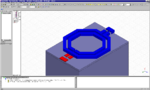
I have a problem with my HFSS 12 simulation. I cannot define the ports correctly so I am having erroneous results. Anyone can advise me on the proper way? I am simulating this transformer at 100 GHz. I have what it seems like 4 ports but I only need 2. I am not sure how you go about and define the other two ports in reference to ground.
Thank you!
Al