Jim cage
Full Member level 2
Hi all,
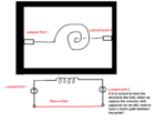
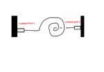
When we simulate an on-chip spiral inductor we typically use lumped ports to interface with the inductor ports (assume you have an inductor with input and output connections). The lumped ports are connected between two conducting materials so one connection is the inductor itself and the other is the PEC material. Between the lumped ports we connect a ground ring for the return current path. I have several questions about this:
1. What if we do not connect the ground ring around the inductor? How severe will the impact be?
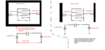
2. What if we connect a MOM cap? Do we still need to have the ground ring? In general, the DC current isn’t flowing through the cap so do we need to have the current return path to Port1 from the reference of Port2?
3. Can we use a waveport instead of lumped port to simulate the inductance?
4. I haven't seen any "return path" for the current when using waveport. What am I missing here? Is it because the nature difference between lumped port and waveport so we can think of the lumped port as a Voltage/Current source?
I am attaching the picture below for demonstration of the "problem".
Regards,
When we simulate an on-chip spiral inductor we typically use lumped ports to interface with the inductor ports (assume you have an inductor with input and output connections). The lumped ports are connected between two conducting materials so one connection is the inductor itself and the other is the PEC material. Between the lumped ports we connect a ground ring for the return current path. I have several questions about this:
1. What if we do not connect the ground ring around the inductor? How severe will the impact be?
2. What if we connect a MOM cap? Do we still need to have the ground ring? In general, the DC current isn’t flowing through the cap so do we need to have the current return path to Port1 from the reference of Port2?
3. Can we use a waveport instead of lumped port to simulate the inductance?
4. I haven't seen any "return path" for the current when using waveport. What am I missing here? Is it because the nature difference between lumped port and waveport so we can think of the lumped port as a Voltage/Current source?
I am attaching the picture below for demonstration of the "problem".
Regards,
Attachments
Last edited: