Continue to Site

Welcome to EDAboard.com

Welcome to our site! EDAboard.com is an international Electronics Discussion Forum focused on EDA software, circuits, schematics, books, theory, papers, asic, pld, 8051, DSP, Network, RF, Analog Design, PCB, Service Manuals... and a whole lot more! To participate you need to register. Registration is free. Click here to register now.

[HFSS] Simulation of finite FSS

Status
Not open for further replies.

KatoAn

Newbie level 5
Joined
Nov 18, 2020
Messages
8
Helped
0
Reputation
0
Reaction score
0
Trophy points
1
Activity points
106
Hi everyone!
I'm simulating a finite FSS using HFSS which has 144 unit cells. We all know that an infinite FSS model can be simulated using floquet port with master-slave boundary. As for a finite FSS, how to set the boundary condition and excitation? An hfss file with simulation model will help me a lot.
Thanks for your help!
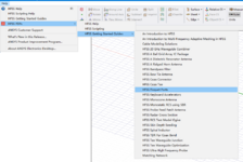
 

Have you checked the HFSS getting started tutorials? There is a file that should have exactly what you're looking for.
Thanks for your reply!

In HFSS getting started guides, I found the file "HFSS floquet ports" which includes the FSS model. However, the FSS model is an infinite FSS which is simulated using master-slave boundary with floquet port.
 

Attachments

  • 1630422890294.png
    1630422890294.png
    92.6 KB · Views: 151

I think you're looking for is the "3D component finite array workflow", take a look at the example "77 GHz 2x2 Phased Array Antenna and Radome based on the 3D Component Finite Array Workflow"

Apologies, it's under File->Open Examples, not Help->Getting Started.

See also this presentation.
 

I think you're looking for is the "3D component finite array workflow", take a look at the example "77 GHz 2x2 Phased Array Antenna and Radome based on the 3D Component Finite Array Workflow"

Apologies, it's under File->Open Examples, not Help->Getting Started.

See also this presentation.
I think in the example "77 GHz 2x2 Phased Array Antenna and Radome based on the 3D Component Finite Array Workflow", the antenna is fed by lumped port, which is different from the FSS. As for an FSS, what we care about is the S11 and S21 (reflection and transmission) and the FSS should be incident by EM wave. The simulation method for finite FSS and finite antenna array should differ from each other in my opinion. What do you think about it?
 

Sure, the are varied applications of the technology. So, you are looking for the response of a finite array with respect to an incident plane wave?

I don't think there's any feasible method to obtaining scattering parameters in this case, unless you integrate the various powers yourself. Since the power will be scattered in three dimensions, the definition of what constitutes an incident or reflected mode is pretty ambiguous (or at least I'm not aware of any commonly used formalities).

If you're just looking at the re-radiated power, you'd want to use the total-field, scattered-field formalism, but I don't think this is compatible with the array workflow.

My guess is in this case, you're limited to solving the entire array. Perhaps you can use some symmetry boundaries to reduce its size (if it's physically symmetric)?
 

Status
Not open for further replies.

Part and Inventory Search

Welcome to EDABoard.com

Sponsor

Back
Top