Continue to Site

Welcome to EDAboard.com

Welcome to our site! EDAboard.com is an international Electronics Discussion Forum focused on EDA software, circuits, schematics, books, theory, papers, asic, pld, 8051, DSP, Network, RF, Analog Design, PCB, Service Manuals... and a whole lot more! To participate you need to register. Registration is free. Click here to register now.

HFSS Modal Analysis of CRLH WG - S-Parameters Above 0 dB Below Cut-Off (LH propagation)

Status
Not open for further replies.

teslameta

Newbie level 5
Joined
Jun 24, 2020
Messages
10
Helped
0
Reputation
0
Reaction score
0
Trophy points
1
Activity points
121
Hi there,

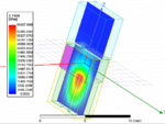
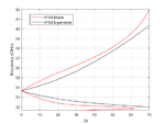
I am trying to replicate the results from this paper (https://ieeexplore.ieee.org/stamp/stamp.jsp?tp=&arnumber=8928575 [open access]) for a CRLH rectangular waveguide antenna with frequency scanning. I have successfully replicated their unit-cell dispersion diagrams within HFSS Eigenmode (see attached image) for the phase constant. In the paper they deduce the leakage constant of a meanderline slot in the via modal analysis of 5 unit cells. I am having a lot of trouble replicating this, observing that my simulations of the 5 unit cells have S21 & S11 above 0 dB in the left-handed region - i.e. the frequencies below the cut-off of the waveguide structure. Additionally, the modal solution report for gamma, shows an attenuation constant of zero at all frequencies - despite there being a 12mm slot cut in to the top wall of the waveguide. This happens irrespective of whether the structure is surrounded by PML or radiation boundaries. I have tested this report before using a standard rectangular waveguide with finite conductivity and match the attenuation constant exactly to theory & exports of s-parameters followed by rlgc conversion.

The last thing I tried was to include a waveguide transition from WR-28 to the CRLH waveguide dimension. It resolved the issues with positive s-parameters but did not affect the problem with the attenuation constant report. Ideally I would just like to simulate the structure without the transition.

I am completely at a loss as to what is going on here. I suspect there may be issues with port impedance and meshing. Could anyone offer any advice on how to solve this? I have attached a copy of the HFSS file (R19) and images of the Eigenmode, S-parameter results.

Thanks in advance!
Sparameters.PNG
beta.PNG
 
Last edited:

Welcome, teslameta!

I don't see your HFSS file attached.

observing that my simulations of the 5 unit cells have S21 & S11 above 0 dB in the left-handed region - i.e. the frequencies below the cut-off of the waveguide structure.
This is probably either your port setup or frequency sweep type. Are you using a driven modal simulation, with wave ports, and a discrete frequency sweep?

Additionally, the modal solution report for gamma, shows an attenuation constant of zero at all frequencies - despite there being a 12mm slot cut in to the top wall of the waveguide. This happens irrespective of whether the structure is surrounded by PML or radiation boundaries. I have tested this report before using a standard rectangular waveguide with finite conductivity and match the attenuation constant exactly to theory & exports of s-parameters followed by rlgc conversion.
That is interesting, can you post a plot of the modal fields generated by the waveport?
 

    teslameta

    Points: 2
    Helpful Answer Positive Rating
Welcome, teslameta!

I don't see your HFSS file attached.


This is probably either your port setup or frequency sweep type. Are you using a driven modal simulation, with wave ports, and a discrete frequency sweep?


That is interesting, can you post a plot of the modal fields generated by the waveport?

Thanks for the warm welcome! That's correct, it is a modal solution with waveports. The waveports are backed by a PEC cap as the model is surrounded by a radiation boundary (I have also tried bringing the boundary to the waveport, but again get the same issues with the S-parameters). I'm using a discrete frequency sweep. I have tried at various solution frequencies in the band between 32 GHz & 42 GHz, all giving the same issue when a transition isn't used. I have also tried a broadband frequency solution setup with the same issue as well.

Are you referring to the port field display? I can get screenshots of that, it would be easier to attach the HFSS file but it won't let me add that filetype to the thread.

Thanks again!
 

Sorry, here it is in a '.zip' file.
 

Attachments

  • EDAHFSS.zip
    113.2 KB · Views: 104


I am having a lot of trouble replicating this, observing that my simulations of the 5 unit cells have S21 & S11 above 0 dB in the left-handed region - i.e. the frequencies below the cut-off of the waveguide structure.

I have simulated your file as provided, and I observe that at 32.2 GHz, the fields on the ports (i.e., plotting the fields at the port locations, not the "port fields display", which only shows the fields solved by the ports' eigenmode solver at the solution frequencies) look significantly different from those of the mode you are solving (i.e., the port fields display). This is mostly caused by the excitation of higher-order modes, which your ports are not configured to accept. Attaching a section of regular waveguide (i.e., WR-28) acts as a filter, since these higher-order modes are likely evanescent, and thus all you would see at the ends is the desired mode.

I'm not sure how you would properly compute the scattering parameters here. Definitely one way is to simulate a larger number of modes on each port (right now you only have one); although you might need a very large number to get a satisfactory solution. Alternatively, you could do what you have already done, and attach feeding waveguides from which you excite and receive waves, as might be the case in real life. I would recommend the second option.

Additionally, the modal solution report for gamma, shows an attenuation constant of zero at all frequencies - despite there being a 12mm slot cut in to the top wall of the waveguide. This happens irrespective of whether the structure is surrounded by PML or radiation boundaries. I have tested this report before using a standard rectangular waveguide with finite conductivity and match the attenuation constant exactly to theory & exports of s-parameters followed by rlgc conversion.

The wave ports gamma doesn't reflect what is inside the structure, only what is contacting the wave port surface. It looks like in your setup the wave ports are significantly displaced from the slots, such that all they see around them is a PEC; hence the zero attenuation.


I wonder if the attenuation constant due to leakage can be deduced with Eigenmode simulations of the unit cell with a slot cut into the broadwall. I found this paper: https://pdfs.semanticscholar.org/ab53/9f42092fb9882337acb6314cd8d439d23284.pdf
It describes using the definition of the Q factor to calculate alpha. Any thoughts on this?

That sounds like an appropriate method, yes.

Good Luck!
 

    teslameta

    Points: 2
    Helpful Answer Positive Rating
Thanks for the detailed response! It seems Eigenmode is the better solution for this problem. I will try both to see if any agreement between the two methods.

Would you suggest a TRL calibration using simulations of two different length lines to remove the affect of the WR transitions?

As for the Q-factor method using HFSS Eigenmode, do you have any advice on how to set this up? Is it correct to use an air-box terminated at the top/sides (y-direction) with PML boundaries? Having periodic boundaries in the propagation direction, and applied to the airbox only? It seems a bit ambiguous because I am not sure if the periodic boundary would only need to be applied to the fields radiating outside the structure, or for the structure and airbox.

Thanks again, you've been a lot of help!
 

Would you suggest a TRL calibration using simulations of two different length lines to remove the affect of the WR transitions?

You can simply use the "deembed" option on the waveports.


As for the Q-factor method using HFSS Eigenmode, do you have any advice on how to set this up? Is it correct to use an air-box terminated at the top/sides (y-direction) with PML boundaries? Having periodic boundaries in the propagation direction, and applied to the airbox only? It seems a bit ambiguous because I am not sure if the periodic boundary would only need to be applied to the fields radiating outside the structure, or for the structure and airbox.

HFSS doesn't like open simulations in its eigenmode solver. What I usually do for situations like this is make a air box slightly larger than the waveguide, and then apply periodic pairs to all sides. It will solve more modes than you would want, but you just need to make sure you're looking at the correct one.

Honestly I think a better option would be to create a driven modal simulation of just the waveguide with the slot; put the ports on the domain edge to simulate an infinite structure, and put a radiation boundary on the transverse axes. This should give you the gamma you're looking for.
 

    teslameta

    Points: 2
    Helpful Answer Positive Rating
Honestly I think a better option would be to create a driven modal simulation of just the waveguide with the slot; put the ports on the domain edge to simulate an infinite structure, and put a radiation boundary on the transverse axes. This should give you the gamma you're looking for.
[/QUOTE]

I have tried to do this but am still having the same issues. I have attached an image of the field at 32.2 GHz, the airbox on top of the structure has radiation boundary applied to it, with waveports at the edge of the structure on the x-axis. Fields leaking from the slot look like they decay immediately.
 

Attachments

  • Capture.PNG
    Capture.PNG
    52.3 KB · Views: 169

Internally to the waveguide structure yes. LH propagation should occur by energy transfer between the waveguide shunts (if it is correct to say that). But what I do not understand is why the electric field does not leak from the slot. Attenuation constant no matter what slot geometry & position I choose is always zero until the cut-off frequency of the waveport. I have brought the slot to the waveport but still get the same result.

It is very frustrating because there is zero documentation on how to calculate the leakage consant due to radiation & all the papers I read only provide figures with no explanation of their method used with HFSS.
 

It is very frustrating because there is zero documentation on how to calculate the leakage consant due to radiation & all the papers I read only provide figures with no explanation of their method used with HFSS.

You should be able to extract it from S-parameters, assuming your metal is PEC and dielectric is vacuum..
 

You should be able to extract it from S-parameters, assuming your metal is PEC and dielectric is vacuum..

Here is what I extract in Modal analysis from S-parameters in comparison to the Eigenmode solve. I can only get this diagram from Modal analysis when I renormalise the port impedance. The renormalised impedance value I used is the Port Z0 at f0. Where f0 is the frequency from the Eigenmode solution where beta = 0. I do not like this method, I would prefer to use the Eigensolver, but when I include the slot in the waveguide with an airbox and PML at the top, the results are nonsense. Any suggestions?
 

Attachments

  • dispersion.png
    dispersion.png
    19.6 KB · Views: 136

Here is what I extract in Modal analysis from S-parameters in comparison to the Eigenmode solve.
Looks correct, but this is the imaginary component, Beta * period. Can you not get the real component, alpha (the attenuation) as well, or is it zero?

I took a look at the eigenmode setup in the file you attached, and there were some issues. The master-slave boundaries need to extend over the entire face of the domain in the propagation direction. You could probably fill in the lower sections outside the WG (currently empty) with a PEC solid. Make sure the master-slave pair cover the PML as well. You can probably get by with perfect-H or perfect-E boundaries on the Y-axes; this should help convergence on the correct modes.
 

Looks correct, but this is the imaginary component, Beta * period. Can you not get the real component, alpha (the attenuation) as well, or is it zero?

I did get the real part but it is nonsense and does not match what is shown in the paper from my first post.

I took a look at the eigenmode setup in the file you attached, and there were some issues. The master-slave boundaries need to extend over the entire face of the domain in the propagation direction. You could probably fill in the lower sections outside the WG (currently empty) with a PEC solid. Make sure the master-slave pair cover the PML as well. You can probably get by with perfect-H or perfect-E boundaries on the Y-axes; this should help convergence on the correct modes.

Thanks for taking a look. I have assigned the waveguide structure as PEC material. How do you extend the Master/Slave boundary to the PML? Is this only in the propagation direction sides of the PML? I have tried this (see attached simulation), by uniting the airbox & PML (Perfect-H boundary on other sides), but still get errors in the results. If you have time, could comment on the file?

Thanks again for your help
 

Attachments

  • OpenUCEignemode.zip
    51.2 KB · Views: 67

I found several notable issues with your simulation. Firstly the domain was the PML, such that your waveguide and space above were filled with the material instead of vacuum. Secondly, the use of a PML in HFSS' eigenmode solver, although usually required, introduces a host of spurious modes that you need to sort through. Since you were only solving for 2 modes, and your minimum frequency fairly low at 21 GHz, all that was being solved was these spurious modes. You can also reduce the number of spurious modes by bringing the PML closer to the structure.

I've corrected your setup; running it now finds the correct mode (well, at least most of the lower band), and as well gives you a finite quality factor from which you should be able to extract loss. If you want to solve the rest of the band(s), I'd suggest creating an additional simulation setup with a higher minimum frequency.

Good luck!
 

Attachments

  • WGtst.aedt.zip
    63.3 KB · Views: 96
Status
Not open for further replies.

Part and Inventory Search

Welcome to EDABoard.com

Sponsor

Back
Top