Continue to Site

Welcome to EDAboard.com

Welcome to our site! EDAboard.com is an international Electronics Discussion Forum focused on EDA software, circuits, schematics, books, theory, papers, asic, pld, 8051, DSP, Network, RF, Analog Design, PCB, Service Manuals... and a whole lot more! To participate you need to register. Registration is free. Click here to register now.

HFSS 90deg phase shift power divider, result shows ~0deg.

Status
Not open for further replies.

StinkyFetus

Newbie
Joined
Feb 20, 2023
Messages
5
Helped
0
Reputation
0
Reaction score
0
Trophy points
1
Activity points
35
Hello
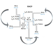
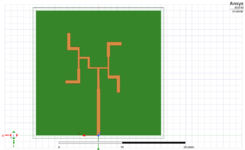
I am working on an parallel antenna feeding Network for RHCP with 4 output ports. The design consists of three parallel (T-junction) sections.
The first section of the feeding network is an anti-phase equal power divider, which provides 180° phase difference. The power divider is connected to each of the anti-phase divider’s output ports with a 90° phase shift between the two output ports. Each output (and the input) is connected to a 50Ω microstrip line which is connected to four 50Ω ohm lumped ports.

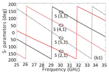
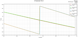
I am expecting 4 output signals with 90° phase difference between each port. In the simulation result i can see the 180° phase difference from the anti-phase equal power divider but the not the 90° phase difference (see images). I am wondering, is the an error to my design or possibly an error in the way I palce the ports. I have tried to remove the 50Ω microstrip line and connecting each output directly to 50Ω ohm lumped ports.
(Project files included)

Design parameters:
Frequency = 28 GHz
Substrate height = 0.254 (er = 3)
Trace height = 0.035
 

Attachments

  • SPARANG.PNG
    SPARANG.PNG
    48.4 KB · Views: 117
  • Network.PNG
    Network.PNG
    39.1 KB · Views: 107
  • FeedingNetworkUnited.zip
    43.1 KB · Views: 91
  • fin.PNG
    fin.PNG
    117.6 KB · Views: 105
Last edited:

Solution
I agree that no extra length exists to create a 90° shift at the two last T-junctions. However, if the 50Ω microstrips lines at the output/input are perfectly matched with the 50Ω ports, the length of those 50Ω microstrip lines should not impact the phase shift.

This is your mistake: the 90° extra length will not do impedance transformation, but provide the 90° phase shift in transmission!
That is true. Let me explain my confusion further. The design stems from the paper "Analytic study on CP enhancement of millimeter wave DR and patch subarray antennas" (2016).

The paper describes the feeding network as follows:

"The parallel feeding network is designed with three parallel T-junction portions containing an anti-phase feeding network and two 908 phase differences in feeding networks. The first section of the feeding network is an anti-phase equal power divider, which provides 180 phase difference between the output ports. Each output port of the anti-phase divider is connected to another power divider with 90 phase shift between the two output ports."

This image is also from this report. The two T-junctions connecting to the output ports are connected directly to 50Ω microstrips. The second attached image is the simulated result from the report.

I agree that no extra length exists to create a 90° shift at the two last T-junctions. However, if the 50Ω microstrips lines at the output/input are perfectly matched with the 50Ω ports, the length of those 50Ω microstrip lines should not impact the phase shift. Regardless, in the paper, they still have a ~90° shift between each port. I guess that in reality/simulation setting, the ports are never perfectly matched. In that case, I guess I need to modify the length of the 50Ω microstrip lines to get the 90° shift.
 

Attachments

  • fin.PNG
    fin.PNG
    117.6 KB · Views: 90
  • result.PNG
    result.PNG
    79.7 KB · Views: 84

I agree that no extra length exists to create a 90° shift at the two last T-junctions. However, if the 50Ω microstrips lines at the output/input are perfectly matched with the 50Ω ports, the length of those 50Ω microstrip lines should not impact the phase shift.

This is your mistake: the 90° extra length will not do impedance transformation, but provide the 90° phase shift in transmission!
 
Solution
I added \[\frac{{\lambda}_{g}}{2 }\] to two ports and \[\frac{{3*\lambda}_{g}}{4 }\] to the other two ports resulting in the desired 90° phase difference between all ports.

thank you for your guidance!
 

Attachments

  • phaseang.PNG
    phaseang.PNG
    76.7 KB · Views: 87
Last edited:

Status
Not open for further replies.

Part and Inventory Search

Welcome to EDABoard.com

Sponsor

Back
Top