Continue to Site

Welcome to EDAboard.com

Welcome to our site! EDAboard.com is an international Electronics Discussion Forum focused on EDA software, circuits, schematics, books, theory, papers, asic, pld, 8051, DSP, Network, RF, Analog Design, PCB, Service Manuals... and a whole lot more! To participate you need to register. Registration is free. Click here to register now.

Hex inverter works, buffer does not. Explain?

Status
Not open for further replies.

TQFP

Junior Member level 3
Joined
Aug 11, 2007
Messages
30
Helped
1
Reputation
2
Reaction score
1
Trophy points
1,288
Location
Florida
Activity points
1,666
I'm in the worst kind of situation. I have made something work, but I don't know why. Very basically:

Output from: FPGA with 3.3V I/O
Input to: Z80 (which is either HMOS or CMOS) NMI input. Z80 is 5V

Does not work, NMI is sporadic:
FPGA ---- Z80 NMI


Does not work, NMI is sporadic. Buffer is MC74VHCT125A Quad Bus Buffer Driver with 5Vcc
FPGA ----|>---- Z80 NMI


This works! Inverter is: SN74ALS04AN with 5Vcc
FPGA ----|>o----|>o---- Z80 NMI


The double inverter is just to keep the polarity of the output from the FPGA the same. The signal is asynchronous in to the Z80 and the delay presented by the inverter is irrelevant (at least is should be...)

Can anyone explain to me what is going on? My primary questions would be:

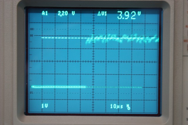
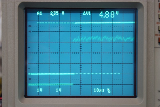
1. Why can't the FPGA directly drive the Z80's input? The FPGA's output is 3.2V loaded (I have measured it) and that is well within the specs for TTL logic '1' and also in the specs for the Z80 (according to the datasheet).

2. Why does the 74125 fail, but the 7404 works? I selected the 74125 specifically because it is a 5V device of the same "stuff" as the Z80. What am I not understanding?

Any insight would be greatly appreciated!

Thanks,
Matthew
 

Sorry I have no idea what could be the type of your FPGA output.
But I like to add that LS series input can be made to float (equivalent to logic state 1).
MOS input will be undetermined if floating so a pullup resistor may be needed (here to 3.3V)

Kerim

Edited:
TTL series input can be made to float but not recommended.
So if a tri-state output drives an input (TTL or MOS) it is always better to add a pullup resistor (its value depends on the circuit, though it is high in general).
 
Last edited:

Forgive me if these issues are too obvious to need asking about:

1. Are you enabling the gate pin of the bus driver IC? If not then output goes to hi impedance, regardless of input level.

2. Did you tie unused inputs of the bus driver IC to ground? (Or else pull them positive depending on your need)? Leaving inputs floating can result in internal oscillations and spikes at power pins. Which can disrupt the section you're using.
 

All output enable pins of the buffer (74125) are tied to ground. I don't ever tri-state the output, it is always high or low. All unused inputs are tied high. The output signal, when testing with my scope, from the 74125 looks just like the output of the back-to-back gates of the 7404. The timing, levels, etc. are all correct for both chips, but the 74125 won't drive the input for some reason.

I can only come up with the idea that the 74125 I chose, like the FPGA, is a CMOS device, and the 7404 is an older ... uh, not CMOS device? TI's datasheet for the sn74als04 does not say what the internal design uses, and it seems there is more going on here than the voltage of the logic levels. The 74125 I chose swings to Vcc - 0.2 and it powered by 5Vcc, so the high is 4.8V (I measured it), and the 7404 does not even go that high.

It is frustrating because I can't make a part selection! The 7404 I have is a DIP that I'm using for the debugging, and I need an SMD part. It is a little unnerving that the difference between my circuit working and not working comes down to some unknown aspect of a chip, and picking a test chip at random, that luckily happens to work, from all the 7404's I have laying around.
 

What is about the input of 74125?
Just as a test, you can add to its input a pull-up resistor to 3.3V (say 4K7) unless you are 100% sure that the FPGA output pin has no 3-state gap in all conditions.

Added:
As you see, my doubt is at the output of FPGA. Perhaps just by adding the pull-up resistor (to 3.3), the FPGA pin can drive directly Z80.
 
Last edited:

As you point out there seems to be no reason one device succeeds where two other devices fail.

Here's pure speculation on my part:

Since two devices fail when they should work, it suggests that your Z80 input is at the borderline of responding normally.

1.

Just for experimentation' sake, put a potentiometer inline with the output of the 7404. See how high the resistance can get until it no longer can drive the Z80 input.

Put the scope leads across the pot and watch if current is flowing through it (either during a hi or a low).

Try the same thing with the output from your FPGA and 74125 as well. See if any more or less current flows in or out. This won't necessarily start driving the Z80 input but you'll find out whether the Z80 input is sourcing or sinking current. (It's probably high impedance in which case any current flow is abnormal.)

There's a chance you chose a particular 7404 which has a healthier ability (if that's the right term), either to drive something high or drive it low. Because your Z80 may need just that higher current in order for internal circuitry to be pulled high or low. It would be the sort of thing that can't be measured directly.

Just implausible speculation on my part.

2.

Try shaping the output pulse a bit.

Soften leading and trailing edges by adding a capacitor connected to V+ or ground. Put a potentiometer in series with it. Dial different degrees of softening.

Or make the leading edge sharper by adding a capacitor in parallel with a potentiometer. Put this assembly in series with the output. Dial different resistances at the potentiometer, to change pulse shape.

Try this with the FPGA and the 74125.

Of course avoid allowing the input voltage to dip below 0 V at any time. Operating requirements for TTL devices warn against applying a voltage outside the zero to 5V range.

I don't know that these experiments will make any difference. Just speculating.
 

What is about the input of 74125?
Added:
As you see, my doubt is at the output of FPGA. Perhaps just by adding the pull-up resistor (to 3.3), the FPGA pin can drive directly Z80.

I don't think FPGA outputs are inherently "glitchy", otherwise they would not be very useful devices. The rest of my circuit is interfacing with the host system very well via a bi-directional data bus, control signals, etc. The interrupt output also works fine for the "level driven" systems.

The FPGA's output in this case is not configured to use the tristate buffer, it is always either logic '0' or logic '1'. Also, the inverter (7404) and buffer (74125) are based on Schottky (or similar) TTL which would remove any glitches or questionable input voltage levels from the FPGA.

Last, testing the outputs on the scope at 10nS per division does not reveal any glitching or irregular voltages. Keep in mind, this is only a 16.6mS signal its fastest rate.

---------- Post added at 20:01 ---------- Previous post was at 19:57 ----------

@Bradtherad. Thanks for the suggestions. I'll be doing some testing later today I hope and some of these are on the list. The signal is pretty solid though, it is not analogue in nature to begin with, and the transitions are pretty quick (7nS to 12nS average.) The Z80 responds to a 1->0 transitions, and it has a minimum high to low time, so I can't soften too much or I will be out of spec.
 

The HCT series is supposed to be TTL level compatible.
However there is a lot more slop than a "real" TTL part's
actual input threshold. And the input stage is liable to
still be cracked on pretty good, with (5-3.3) on the PMOS.
The device will be pretty well lit up even if it puts out the
desired logic state.

There are level shifting buffers out there, it would be better
to use one that really fits at both ends.

You say that the outputs look the same and the results
differ. Perhaps there is a hookup error or something. That,
or the marginality is within the "eyeball range of error".
 

The HCT series is supposed to be TTL level compatible.
There are level shifting buffers out there, it would be better
to use one that really fits at both ends.

The MC74VHCT125A datasheet specifically states:

"The VHCT inputs are compatible with TTL levels. This device can be used as a level converter for interfacing 3.3 V to 5.0 V, because it has full 5.0 V CMOS level output swings."

I'm powering the 125A from the host 5V side, and the logic '1' input is 3.3V from the FPGA (measured). The Vih (voltage input high) of the 125A is 2.0V, so I'm easily be driving it from the FPGA. I measured the 125A output at 4.85V for a logic '1'.
 

It's apparent you know what you're doing. I'll bet most of us have started to fix something and got it working, but without knowing what we specifically did to fix it.

In that case when the item belonged to someone else I had to tell them 'I don't know what I did, but it's working now.' But I didn't know if it was really fixed. Or if they had trouble with it later, and whether they said 'that Brad fellow doesn't know what he's doing.'

----------------------------------------

Yes, softening the signal isn't likely to help. The opposite is better, to make the transition faster. It would have been easy for me to suggest that. Fast transitions work best with digital devices. It's just that I don't know of an easy way to speed up a slew rate.

Another experiment to try... Comparing the 7404 and 74125 outputs. Do you find that the 7404 goes to a lower voltage when it goes low?

Or does the 7404 have lesser impedance when it goes low than the 74125?

Is the input at the Z80 being pulled down closer to zero with the 7404 than with the 74125?

A few hundredths of a volt could be the difference. This must be a borderline difference within the Z80, between working and not working. I don't know for sure, I'm just speculating.
 

I have some images from my scope:


The one with a single trace is the original signal as produce by the chip I am reproducing (TMS9918A). The image with two signals is before and after the hex inverter stage, like this:

FPGA ------|>---[tp1]---|>o------|>o---[tp2]--- Z80 #NMI

The cursor is showing the voltage out of the 125A buffer. Both the 74125 and 7404 pull to 0V. If I take the interrupt from tp1, it does not work. If I take it from tp2, it does. I don't know how to be any more concise than that.

I also just tried using a mosfet (BSS138) source follower, that works too! The FPGA output goes to the gate, the drain is tied to 5V, the source has a resistor to ground. I take the output from the source. Maybe this whole problem is totally current related...

Let's see, the resistor I grabbed is 490-ohm. Vcc is 5V, so that is 10.2mA max through the resistor. The FPGA can drive up to 16mA though.

By the way, I tried a resistor and capacitor to soften the transition... did't help.
 

It seems the only difference between tp1 and tp2 (or adding a mosfet) is the very small time delay (on the scope pic it seems about 2us but I think it is much less actually).
To be sure that this delay is not the cause, I am afraid you need to write a very simple Z80 program which consists of and idle loop and the interrupt of interest. So that you will be 100% sure that the problem is hardware and not software if this simple program cannot detect the interrupt signal (since Z80 has nothing else to do).
 

Actually, the signals are very gittery (and slow, so they flicker too), even the original 9918A chip in the first image has a variable time in the low state from the time of the trigger. The low states fluctuate together, it is just when the camera captured the screen.

The #NMI input to the Z80 is asynchronous, so a delay through the gates would not affect the operation.
 

I believe you know very well what you are doing... So I may say that I am fortunate this doesn't happen to me... because I won't be able to sleep well for days till I find the logical answer or... I declare it as another divine secret and go to sleep :grin:

Added:
Is the 3.3V supply noisy as it is seen on the pics?

Now this is called a very good news... Congratulations :grin:
 
Last edited:

Thanks. I hate not understanding! Actually I just found a solution. A 100-ohm resistor inline with the FPGA's output! Seems the Z80's #NMI does not like to go all the way to ground or something... 1 stupid resistor and it all works great... ugh. I like easy solutions, but I went through hell getting here! Thanks everyone for the suggestions and feedback.
 

Good going.

Despite your exasperation at the unexpected way the devices behaved...

Nevertheless the Sherlock Holmes in you enjoys a mystery.
 

Status
Not open for further replies.

Part and Inventory Search

Welcome to EDABoard.com

Sponsor

Back
Top