172pilot
Newbie level 2
Hi,
I've got a project that I THOUGHT was going to be simple, but has turned out to be a bit tough..
I have a small toy dog that runs off of 2x AA batteries (3v) and when switched on, just walks around and "barks". What I need to do, is to use a big button (think "Easy Button" at staples) to trigger the dog to turn on for a specified amount of time (5 seconds or so).
This will be used for teaching special needs children.
My initial thought was to embed a small 8 pin microcontroller in the dog, and expose only a 1/8" jack to connect to an external switch that the school already has for use with similar commercially sold toys, but to open the toy and modify it in that way would be difficult, and I'm afraid my "toy surgeon" skills would mean the toy would never be the same, so I have opted to design it such that the toy will stay on, but I'm going to interrupt the power to the toy through 2 wires running to it from whatever button I choose (Since the "smarts" get moved outside the toy in this situation, I think I'm going to use an actual Staples brand "easy button" because it already can house the circuitry and batteries for my circuit.
OK.. So, that's the requirement.. now, my thought of the design..
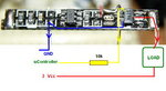
My initial thought was that I'd program a microcontroler to monitor the button, do the timing, and use a TTL output to turn "on" to turn on the toy. THis much is a piece of cake.. no problem, already have code to test with. My problem is that from the TTL output, I had HOPED to just use a transistor to ground the toy and turn it on. In the past, I've use an NPN transistor to switch on a relay for other purposes. I was hoping that my toy would be the load, like the relay was, and it would turn on.
Unfortunately, this isn't working for me. It's killing the whole circuit. I THINK it might be that the toy is taking too much current, and killing the microcontroller, but I have verified that the micro is still running because if I hook an LED to the output, even though the LED goes dark when I connect the toy, the duty cycle of the counter continues while dark, and it lights back up in the same phase of my loop when I remove the toy (I hope that makes sense)...
Does anyone have any ideas? What else can I answer about my attempts? I've tried to upload a .GIF file picture of the basic idea I am trying to duplicate regarding the transistor, but I dont know if it went or not, so hopefully I've explained it in the text!
Thanks in advance for any help!
-Steve
I've got a project that I THOUGHT was going to be simple, but has turned out to be a bit tough..
I have a small toy dog that runs off of 2x AA batteries (3v) and when switched on, just walks around and "barks". What I need to do, is to use a big button (think "Easy Button" at staples) to trigger the dog to turn on for a specified amount of time (5 seconds or so).
This will be used for teaching special needs children.
My initial thought was to embed a small 8 pin microcontroller in the dog, and expose only a 1/8" jack to connect to an external switch that the school already has for use with similar commercially sold toys, but to open the toy and modify it in that way would be difficult, and I'm afraid my "toy surgeon" skills would mean the toy would never be the same, so I have opted to design it such that the toy will stay on, but I'm going to interrupt the power to the toy through 2 wires running to it from whatever button I choose (Since the "smarts" get moved outside the toy in this situation, I think I'm going to use an actual Staples brand "easy button" because it already can house the circuitry and batteries for my circuit.
OK.. So, that's the requirement.. now, my thought of the design..
My initial thought was that I'd program a microcontroler to monitor the button, do the timing, and use a TTL output to turn "on" to turn on the toy. THis much is a piece of cake.. no problem, already have code to test with. My problem is that from the TTL output, I had HOPED to just use a transistor to ground the toy and turn it on. In the past, I've use an NPN transistor to switch on a relay for other purposes. I was hoping that my toy would be the load, like the relay was, and it would turn on.
Unfortunately, this isn't working for me. It's killing the whole circuit. I THINK it might be that the toy is taking too much current, and killing the microcontroller, but I have verified that the micro is still running because if I hook an LED to the output, even though the LED goes dark when I connect the toy, the duty cycle of the counter continues while dark, and it lights back up in the same phase of my loop when I remove the toy (I hope that makes sense)...
Does anyone have any ideas? What else can I answer about my attempts? I've tried to upload a .GIF file picture of the basic idea I am trying to duplicate regarding the transistor, but I dont know if it went or not, so hopefully I've explained it in the text!
Thanks in advance for any help!
-Steve