Continue to Site

Welcome to EDAboard.com

Welcome to our site! EDAboard.com is an international Electronics Discussion Forum focused on EDA software, circuits, schematics, books, theory, papers, asic, pld, 8051, DSP, Network, RF, Analog Design, PCB, Service Manuals... and a whole lot more! To participate you need to register. Registration is free. Click here to register now.

Help with ULN2003A motor driver

Status
Not open for further replies.

loyaci

Newbie level 5
Joined
Mar 24, 2011
Messages
10
Helped
2
Reputation
4
Reaction score
2
Trophy points
1,283
Activity points
1,348
Hello friends...

i want to interface the ULN2003A with 12vdc stepper motor, i put a 5v in the inputs of the motor driver (5v for each in a sequence) but the output of the motor driver is low (0.6v) and cannot move the motor of course.
i change the ic and also increase the input voltage and still have the same problem

---------- Post added at 03:11 ---------- Previous post was at 03:08 ----------

43_1303690181.jpg


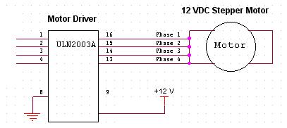
this is the schematic for the circuit that i have done
 
Last edited:

Given that on your schematic the stepper only has 4 wires, I have to assume it's a bipolar one. These are a pain to drive with ULN2003 (or ULN2803 or other Darlington arrays) because the chips are designed to sink current and you need to be able to send both high and low voltages to each of the four wires.

You'd normally use H-bridge ICs to drive a bipolar stepper but if you are absolutely set on using ULN2003, you can float the wires off of a motor supply voltage on power resistors (and they will get really hot) and then sink with ULN if you need low voltage or let go if you need high. There is a schematic and Arduino code for just that here. The sample is based on ULN2803 but it's the same chip only 8 arrays rather than 7.

Good luck!
 

i used a schemit trigger to convert the outputs of the uln2003a from low (0.6v) to high (5v) and then connect it to the motor and it works. i think i will need voltage regulator if i want to increase the voltage more.

thanks


i used a schemit trigger to convert the outputs of the uln2003a from low (0.6v) to high (5v) and then connect it to the motor and it works. i think i will need voltage regulator if i want to increase the voltage more.

thanks

Augmenting an ULN darlington array chip kinda defeats the purpose of using it.

At 60 cents per IC it's supposed to be a quick and cheap way of powering something that needs more sink than your logic (or MCU) can provide. If you find yourself needing to add more switches, you're much better off just abandoning the ULN idea and using a proper IC for what you're doing.

In this case a quad half-H-bridge IC such as SN754410 will do the job much nicer 'cause it'll both source and sink current (and more of it than UNL2003, too). It'll be something like 5 times more expensive but it''s still an under-$5 chip.

Come to think of it, depending on the application you might as well look at an even higher specialized stepper motor driver chip such as Allegro 3967. It'll be a couple $ more expensive still but it will take just the step and direction signals and do microstepping on top of all its other goodness!
 
thank you friends,
i forget to tell, the motor is a unipolar stepper motor and it has 5 wires (4 phases and 1 GND). so which motor driver is the best? H-bridge IC (SN754410) or ULN's?
 
A unipolar motor can be driven fine using something like
uln2003-stepper.gif


ULN will work fine up to 500mA or you can use 2 outputs together for 1A.

Alex
 
ULN will work fine up to 500mA or you can use 2 outputs together for 1A.
You should also consider the graph "Allowable output current as a function of duty cycle". For static load situations 1A is out of bounds.
 
You should also consider the graph "Allowable output current as a function of duty cycle". For static load situations 1A is out of bounds.

Yes, you are correct, I should have checked the datasheet first.

Alex
 
i make the connection in the schematic and the motor works perfectly, this is really helpfull.
the problem that i put an LED in each output of the driver and when i take it off the motor works and drived very will by the ULN2003A

thank you
 
If you want to use leds in the output of the ULN then you have to connect the led cathode to the ULN output (one led each output) and then the anode through a resistor for each led to the positive supply.

Alex

edit: since you feed the coil in parallel with the led it will probably not work because the coil has a much lower resistance.

Alex
 

Status
Not open for further replies.

Part and Inventory Search

Welcome to EDABoard.com

Sponsor

Back
Top